Pepperl+Fuchs
Choose a subcategory:
Show all categories
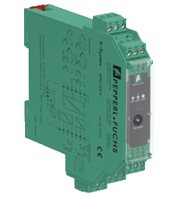
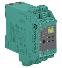
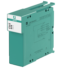
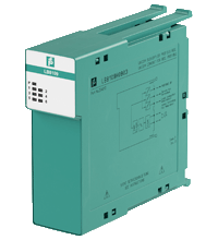
- 2-channel signal conditioner
- 24 V DC supply (Power Rail)
- Thermocouple, RTD, potentiometer or voltage input
- Usable as signal splitter (1 input and 2 outputs)
- Voltage output 0/1 V ... 5 V
- Configurable by PACTware
- Line fault (LFD) and sensor burnout detection
- Up to SIL 2 acc. to IEC 61508/IEC 61511
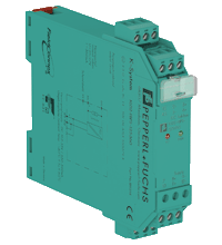
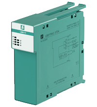
1-channel isolated barrier
24 V DC supply (Power Rail)
Thermocouple, RTD, potentiometer or voltage input
1-channel isolated barrier
24 V DC supply (Power Rail)
1-channel isolated barrier
24 V DC supply (Power Rail)
Voltage input 0 V ... -20 V
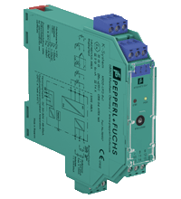
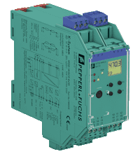
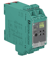
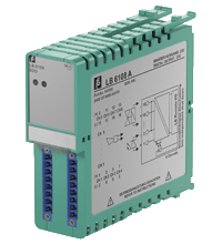
- 1-channel signal conditioner
- 24 V DC supply (Power Rail)
- Strain gauge input (full or half bridge)
- Output 0 mA ... В± 20 mA or 0 V ... В± 10 V
- 2 relay contact outputs
- Programmable high/low alarm
- Configurable by PACTware or keypad
- RS-485 interface
- Line fault detection (LFD)
- 1-channel isolated barrier
- 24 V DC supply (Power Rail)
- Strain gauge input (full or half bridge)
- Output 0 mA ... В± 20 mA or 0 V ... В± 10 V
- 2 relay contact outputs
- Programmable high/low alarm
- Configurable by PACTware or keypad
- RS-485 interface
- Low response time
- Line fault detection (LFD)
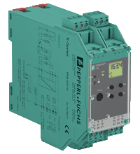
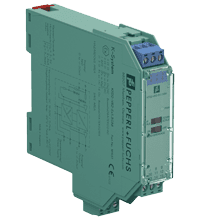
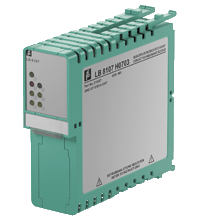
- 1-channel signal conditioner
- Universal usage at different power supplies
- Thermocouple, RTD, potentiometer or voltage input
- Redundant TC input
- Current output 0/4 mA ... 20 mA
- 2 relay contact outputs
- Configurable by PACTware or keypad
- Line fault (LFD) and sensor burnout detection
- Up to SIL 2 acc. to IEC 61508/IEC 61511

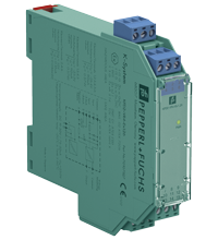
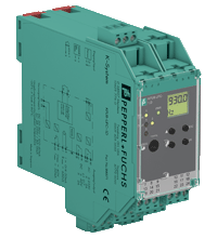
- 1-channel signal conditioner
- Universal usage at different power supplies
- Input for 2- or 3-wire sensors, NAMUR sensors or dry contacts
- Input frequency 1 mHz ... 10 kHz
- Current output 0/4 mA ... 20 mA
- Relay contact and transistor output
- Start-up override
- Line fault detection (LFD)
- Up to SIL 2 acc. to IEC 61508/IEC 61511
- 2-channel signal conditioner
- Universal usage at different power supplies
- Dry contact or NAMUR inputs
- Input frequency 1 mHz ... 1 kHz
- Current output 0/4 mA ... 20 mA
- Relay contact and transistor output
- Start-up override
- Configurable by PACTware or keypad
- Line fault detection (LFD)
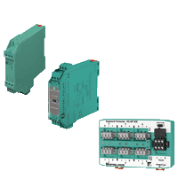
- Output: 25 ... 27 V/360 mA
- For most fieldbus applications
- High-power trunk for high device count and long cable lengths
- Installation in Zone 2/Class I, Div. 2
- For FOUNDATION Fieldbus H1
- Fixed, high-availability terminator
- No spacing required between modules
- Output: 24 ... 26 V/400 mA
- For extension of fieldbus segments
- High-power trunk for high device count and long cable lengths
- Installation in Zone 2/Class I, Div. 2
- For FOUNDATION Fieldbus H1 and PROFIBUS PA
- Fixed, high-availability terminator
- High efficiency, low heat dissipation
- Supply via Power Rail
- Power supply of fieldbus segments according to IEC 61158-2
- Signal repeater for fieldbus topologies in accordance to Entity
- 70 mA supply of the field side
- Improves the fieldbus signal
- Extension of the transmission distance by means of opening a new fieldbus segment
- Integrated bus terminations
- Removable terminals and Power Rail connection for simple installation
- Supply via Power Rail

- Power supply of fieldbus segments according to IEC 61158-2
- Signal repeater for fieldbus topologies in accordance to FISCO
- 100 mA supply of the field side
- Improves the fieldbus signal
- Extension of the transmission distance by means of opening a new fieldbus segment
- Integrated bus terminations
- Removable terminals and Power Rail connection for simple installation
- Supply via Power Rail
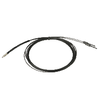
Plastic fiber optic

- Comprehensive diagnostics for the fieldbus physical layer
- Module and motherboard for retrofit of any installation
- Precise measurements through passive circuits
- For commissioning, online monitoring and troubleshooting
- For FOUNDATION Fieldbus H1 and PROFIBUS PA
- Installation in Zone 2/Class I, Div. 2
- System state and fault indication via LEDs
- Display of data in the safety of the control room
- Full software integration into PCS and PAM possible
- System integration kit for Advanced Diagnostics
- PCS integration via Diagnostic Manager or device DTM
- Simple automatic setup of Advanced Diagnostics
- Common alarm handling
- For FOUNDATION Fieldbus and PROFIBUS PA
- Installation in Zone 2
- System integration kit for Advanced Diagnostics
- PCS integration via Diagnostic Manager or device DTM
- Simple automatic setup of Advanced Diagnostics
- Alarm handling and integrated I/O for cabinet monitoring/control
- For FOUNDATION Fieldbus and PROFIBUS PA
- Installation in Zone 2
Complete hardware for connection of FOUNDATION Fieldbus H1 field devices to the host system of your choice
Complete hardware for connection of PROFIBUS PA field devices to a DP-Master
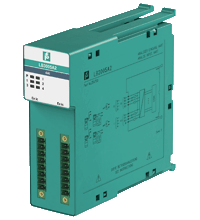
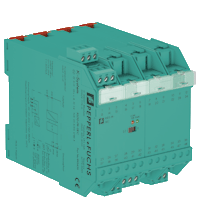
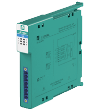
- 4-channel
- Power supply for 2-wire transmitters with 4 mA ... 20 mA
- Installation in Zone 2 or safe area
- Supply circuit 15 V (20 mA)
- Input from active signals of 4-wire transmitters
- HART communication via field bus or service bus
- Simulation mode for service operations (forcing)
- Line fault detection (LFD): one LED per channel
- Permanently self-monitoring
- Module can be exchanged under voltage
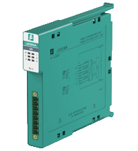
- 4-channel
- Power supply for 2-wire transmitters with 4 mA ... 20 mA
- Installation in Zone 2 or safe area
- Supply circuit 21.5 V (4 mA)
- HART communication via field bus or service bus
- Simulation mode for service operations (forcing)
- Line fault detection (LFD): one LED per channel
- Permanently self-monitoring
- Module can be exchanged under voltage
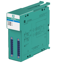
- 4-channel
- Inputs Ex ia
- Mounting in Zone 2, Class I/Div.2 or in the safe area
- Power supply for 2-wire transmitters with 4 mA ... 20 mA
- Supply circuit 15 V (20 mA)
- Input from active signals of 4-wire transmitters
- HART communication via field bus or service bus
- Simulation mode for service operations (forcing)
- Line fault detection (LFD): one LED per channel
- Permanently self-monitoring
- Module can be exchanged under voltage
- 4-channel
- Inputs Ex ia
- Mounting in Zone 2, Class I/Div.2 or in the safe area
- Power supply for 2-wire transmitters with 4 mA ... 20 mA
- Supply circuit 15 V (20 mA)
- HART communication via field bus or service bus
- Simulation mode for service operations (forcing)
- Line fault detection (LFD): one LED per channel
- Permanently self-monitoring
- Module can be exchanged under voltage
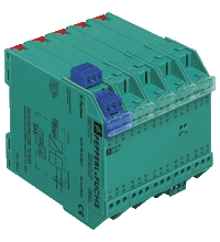
- 8-channel
- Outputs Ex ib
- Mounting in Zone 2, Class I/Div.2 or in the safe area
- Module can be exchanged under voltage
- Galvanic group isolation
- Line fault detection (LFD)
- Positive or negative logic selectable
- Simulation mode for service operations (forcing)
- Permanently self-monitoring
- Output with watchdog
- Output with bus-independent safety shutdown
- Interface between the I/O modules and the PCS/PLC
- Com unit for 80 analog or 184 digital channels
- Communication via MODBUS RTU
- Mounting in Zone 2, Class I/Div.2 or in the safe area
- HART communication via service bus
- Configuration via FDT 1.2 DTM
- Non-volatile memory for configuration and parameter settings
- Self configuration in redundant systems
- Permanently self-monitoring
- Outputs drive to safe state in case of failures
- Module can be exchanged under voltage
- Interface between the I/O modules and the PCS/PLC
- Com unit for 80 analog or 184 digital channels
- Communication via PROFIBUS DP
- Mounting in Zone 2, Class I/Div.2 or in the safe area
- HART communication via PROFIBUS DP V1 or service bus
- Configuration via FDT 1.2 DTM
- Configuration in run (CiR) for any PCS
- Non-volatile memory for configuration and parameter settings
- Self configuration in redundant systems
- Permanently self-monitoring
- Outputs drive to safe state in case of failures
- Module can be exchanged under voltage
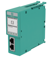
- Interface between the I/O modules and the PCS/PLC
- Com unit for 80 analog or 184 digital channels
- Communication via MODBUS TCP
- Mounting in Zone 2, Class I/Div.2 or in the safe area
- HART communication via MODBUS TCP or service bus
- Configuration via FDT 1.2 DTM
- Non-volatile memory for configuration and parameter settings
- Self configuration in redundant systems
- Permanently self-monitoring
- Outputs drive to safe state in case of failures
- Module can be exchanged under voltage
- Interface between the I/O modules and the PCS/PLC
- Mounting in Zone 2, Class I/Div.2 or in the safe area
- Non-volatile memory for configuration and parameter settings
- Communication via PROFINET
- HART communication via PROFINET and HART I/P