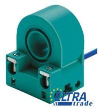
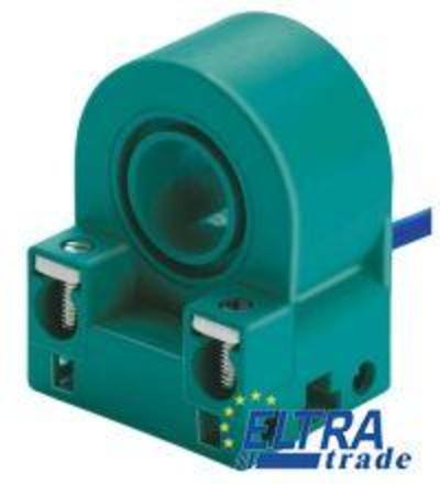
Pepperl+Fuchs PL4-F25-N4-S
Inductive sensor

Housing material: PBT, Rated operating distance: 3 mm, Connection (valve side): screw terminals, Output type: 2-wire, Installation: embeddable mountable, Type of voltage: DC
- Overview
- Comments
| General specifications | ||
| Switching element function | DC | |
| Rated operating distance | 3 mm | |
| Installation | flush mountable | |
| Output polarity | NAMUR | |
| Assured operating distance | 0 ... 2.43 mm | |
| Reduction factor rAl | 0.5 | |
| Reduction factor rCu | 0.4 | |
| Reduction factor r304 | 1 | |
| Reduction factor rSt37 | 1.2 | |
| Reduction factor rBrass | 0.63 | |
| Nominal ratings | ||
| Nominal voltage | 8.2 V (Ri approx. 1 kOm) | |
| Operating voltage | 5 ... 25 V | |
| Switching frequency | 0 ... 100 Hz | |
| Hysteresis | typ. 5 % | |
| Reverse polarity protection | reverse polarity protected | |
| Current consumption | ||
| Measuring plate not detected | greater or equal 3 mA | |
| Measuring plate detected | less than or equal to 1 mA | |
| Switching state indicator | LED, yellow | |
| Valve status indicator | LED, yellow | |
| Compliance with standards and directives | ||
| Standard conformity | ||
| NAMUR | EN 60947-5-6:2000 | |
| Electromagnetic compatibility | NE 21:2007 | |
| Ambient conditions | ||
| Ambient temperature | -25 ... 100 °C (-13 ... 212 °F) | |
| Storage temperature | -40 ... 100 °C (-40 ... 212 °F) | |
| Mechanical specifications | ||
| Connection (system side) | screw terminals | |
| Core cross-section (system side) | up to 2.5 mm2 | |
| Connection (valve side) | screw terminals | |
| Core cross-section (valve side) | up to 2.5 mm2 | |
| Housing material | PBT | |
| Sensing face | PBT | |
| Note | Installation in housing | |
| ATEX 1G | ||
| Specific conditions | ||
| Lead insertion | The connection cables should either be fixed when laid and mechanically protected or installed in such a way, that a force of 30 N applied in the direction of the cable inlet for one hour, does not lead to any visible displacement of the cable connections, even though the cable sheathing is displaced, see also IEC 60079-11. Depending on the type of installation, a suitable cable in accordance with Type A oder B of IEC 60079-14, must be used. | |
| ATEX 2G | ||
| Specific conditions | ||
| Lead insertion | The connection cables should either be fixed when laid and mechanically protected or installed in such a way, that a force of 30 N applied in the direction of the cable inlet for one hour, does not lead to any visible displacement of the cable connections, even though the cable sheathing is displaced, see also IEC 60079-11. Depending on the type of installation, a suitable cable in accordance with Type A oder B of IEC 60079-14, must be used. | |
| General information | ||
| Use in the hazardous area | see instruction manuals | |
| Category | 1G- 2G | |

Comments
No comments yet