Encoder Basics: Selecting the Right Type
09.01.2022
If you are working on an electromechanical system or a robotics project, you will need to measure and control the motion of some parts. Encoders can help you with this task. To select a device that will provide correct positional feedback from the moving parts, you should know what type of encoder is best for your system.
Encoders come with many options. They are built using different materials and technologies. They also vary in size, mount type, precision, accuracy, energy consumption, and price. Getting familiar with the encoder basics will help you make an informed buying decision.
Define Your Project Needs
Encoders increase a system’s complexity. If your system operates with an open-loop controller, uses stepper motors, Hall sensors, limit, or proximity switches, you might not need an encoder. But if you need a closed-loop control system, make sure to understand its specifics and operating environment before selecting an encoder.
Factors that influence encoder choice:
- High, regular, or extremely slow speed of motion.
- Type of input signals that your controller receives.
- Mounting type and location of the encoder (on the load, on the motor, etc.).
- Required system accuracy.
- The flexibility of your project design.
- Environmental conditions (dust, water, heat, vibrations, etc.).
- The number of encoders you need.
- Allocated budget.
Type of Encoder Technology: Optical, Magnetic, or Capacitive
All encoders fall into three distinct camps based on their manufacturing technology. Your environmental conditions, energy needs, precision, and speed requirements will determine what kind of setup you need. It is not necessary to choose the encoder with the highest resolution. In each case, the encoder has to be matched to the task at hand. A workpiece feeding system, when machining metal surfaces, has to provide accurate positioning, so in this case, a high resolution plays an important role.
For speed stabilization systems, on the other hand, a relatively low-resolution encoder can be used for high angular speeds with the same pulse repetition rate. They can be divided into solid shaft encoders and hollow shaft encoders. The former are usually supplied with a transition coupling that connects the encoder shaft and the shaft of the mechanism (motor).
Optical
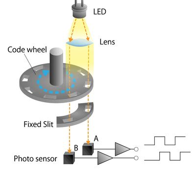
The modern absolute optical encoder is an extremely complex device. When designing a high-resolution optical encoder, designers are faced with a multitude of conflicting factors that greatly affect the long-term accuracy and reliability of the encoder. Optical encoders offer very high resolution and accuracy, as well as superior dynamic performance, and are suitable for use in areas with intense magnetic fields.
Since the rotation of the encoder discs is a fully mechanical process, these devices cannot lose absolute position information in the event of a temporary power failure of the device. Backup batteries are not required.
Magnetic
Magnetic encoders detect angular position using magnetic-field technology. A permanent magnet mounted on the encoder shaft creates a magnetic field, which is measured by a sensor that generates a unique absolute position value. Magnetic encoders are reliable, durable and compact. The battery-less, gearless design offers mechanical simplicity and lower cost compared with optical encoders. Their compact size allows them to be used in very confined spaces.
- Performs well in difficult environments with excessive dust or humidity.
- Consumes less energy.
- Can be affected by stray magnetic fields.
- May require magnetic shielding to provide accurate readings.
Capacitive
The capacitive encoder applies a reference signal to detect a change in capacitance. It usually consists of a rotor sandwiched between a stationary transmitter and a stationary receiver. A high-frequency current flows through the rotor. With each rotation, it distorts the AC field according to a predictable pattern. The modulated signal is converted by the receiver into a series of pulses and passed on to the controller.
- Consumes the least amount of energy.
- Offers accurate, high-resolution measurement.
- Performs reasonably well in difficult environments.
- Sensitive to electrostatic build-up.
- Works with lower speeds than optical encoders.
Types of Measurement: Incremental, Absolute or Pseudo-Absolute
Encoders capture and report positional data in two different ways: incremental and absolute. There’s also a hybrid option.
Incremental
Incremental encoders generate a sequence of pulses at their output, which is fed to counters or other receivers, and the number of pulses or edges is counted. Immediately after power-up, the measured position is unknown, since the incremental encoder output only has information about the incremental position. After power-up, a Homing procedure is started to tie the counting to the origin of the machine or machine coordinate system.
The system makes a trial movement and finds some zero reference points. At the moment of passing through these points, a reference to the origin of coordinates is set. After this point, pulse counting from the encoder output can accurately determine the position of the actuator, but only if the high pulse rate or interference allows this to be done. Failure of pulse counting from the incremental encoder output leads to movement errors, to inoperability of the system as a whole, and requires, at the very least, a re-counting.
Absolute
From the output information of such encoders, it is possible to judge the position of its rotor, regardless of whether its power supply has been switched off or not. A distinction is made between single-turn and multi-turn absolute encoders.
A single-turn absolute encoder converts the angle of rotation of the encoder shaft into a digital code. Each position within a revolution has a different code value. The digital code can take many forms: parallel code (binary, binary-decimal, Gray's, etc.) and sequential code, where position information is contained in digital messages generated at the encoder output (such as SSI, BiSS, CAN Open, etc.).
The multi-turn absolute encoder generates position information not only within a revolution but also counts the number of full rotations of the encoder shaft. The number of full turns stored in its memory can be up to several hundred thousand. The form of representation of the digital code is serial and/or parallel code.
Quite often in servo drives, a multi-turn absolute encoder is used in conjunction with an external battery which is connected to special terminals on this encoder. Without a battery, the drive position memory is lost after a power failure. And such an encoder without a battery is used as an incremental encoder.
Conclusion
Now that you are familiar with the role of encoders, their basic types, differences, pros, and cons, use this information to find the one that will suit your project. If you have additional questions or need help with the selection process, don’t hesitate to contact the seller or even