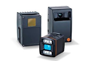
IFM Vision assistant

- PMD 3D ToF (Time of Flight) camera for the output of 3D image data
- Device interfaces: digital input/output
- Ethernet
- Angle of aperture 60° x 45° (horizontal x vertical)
- Image resolution 176 x 132 pixels
- Connector, Outputs: max. 2 (configurable)
AFL-12A-ATOM-N270/WT-R/1GB-R20

Max. field of view size: 640 x 480 mm, Infrared lighting 850 nm, Max. field of view size: 640 x 480 mm, Outputs: max. 5 (configurable) / 24 V PNP

Max. field of view size: 1320 x 945 mm, Infrared lighting 850 nm, Outputs: max. 5 (configurable) / 24 V PNP

Max. field of view size: 400 x 300 mm, Infrared lighting 850 nm, Outputs: max. 5 (configurable) / 24 V PNP
Max. field of view size: 400 x 300 mm, Infrared lighting 850 nm, Outputs: max. 5 (configurable) / 24 V NPN

Max. field of view size: 640 x 480 mm, Infrared lighting 850 nm, Max. field of view size: 640 x 480 mm, Outputs: max. 5 (configurable) / 24 V NPN

Max. field of view size: 1320 x 945 mm, Infrared lighting 850 nm, Outputs: max. 5 (configurable) / 24 V NPN

Max. field of view size: 640 x 480 mm, Illumination: white light, Max. field of view size: 640 x 480 mm, Outputs: max. 5 (configurable) / 24 V PNP

Max. field of view size: 640 x 480 mm, Illumination: white light, Max. field of view size: 640 x 480 mm, Outputs: max. 5 (configurable) / 24 V NPN

Max. field of view size: 1320 x 945 mm, Illumination: white light, Outputs: max. 5 (configurable) / 24 V PNP

Max. field of view size: 1320 x 945 mm, Illumination: white light, Outputs: max. 5 (configurable) / 24 V NPN

Max. field of view size: 400 x 300 mm, Illumination: white light, Outputs: max. 5 (configurable) / 24 V PNP

Max. field of view size: 400 x 300 mm, Illumination: white light, Outputs: max. 5 (configurable) / 24 V NPN
Max. field of view size: 640 x 480 mm, Lighting: infrared (850 nm), Max. field of view size: 640 x 480 mm, Outputs: max. 5 (configurable) / 24 V PNP

Max. field of view size: 640 x 480 mm, Lighting: infrared (850 nm), Max. field of view size: 640 x 480 mm, Outputs: max. 5 (configurable) / 24 V NPN

Max. field of view size: 1320 x 945 mm, Lighting: infrared (850 nm), Outputs: max. 5 (configurable) / 24 V NPN

Max. field of view size: 400 x 300 mm, Lighting: infrared (850 nm), Outputs: max. 5 (configurable) / 24 V PNP

Max. field of view size: 400 x 300 mm, Lighting: infrared (850 nm), Outputs: max. 5 (configurable) / 24 V NPN
PMD 3D camera, Angle of aperture 40° x 30°, (horizontal x vertical), Connector, Outputs: max. 2 (configurable) / 24 V PNP
3D camera, PMD 3D ToF (Time of Flight) camera for the output of 3D image data, Device interfaces: digital input/output, Ethernet, Angle of aperture 40° x 30° (horizontal x vertical), Image resolution 176 x 132 pixels, Connector, Outputs: max. 2 (configurable) / 24 V PNP/NPN to IEC 61131-2

3D camera, PMD 3D ToF (Time of Flight) camera for the output of 3D image data, Device interfaces: digital input/output, Ethernet, Angle of aperture 60° x 45° (horizontal x vertical), Image resolution 176 x 132 pixels, Connector, Outputs: max. 2 (configurable) / 24 V PNP/NPN to IEC 61131-2
O3DIRDKG/E1/GM/S/70
3D camera, PMD 3D ToF (Time of Flight) camera for the output of 3D image data, Device interfaces: digital input/output, Ethernet, Angle of aperture 40° x 30° (horizontal x vertical), Image resolution 176 x 132 pixels, Connector, Outputs: max. 2 (configurable) / 24 V PNP/NPN to IEC 61131-2
O3DIRDKG/E1/GM/S/60
O3DIRDKG/E1/GM/S/60
O3DIRDKG/E1/GM/W/70


Vision Assistant from IFM electronic is a new approach to sensor programming. The operating software for IFM sensors and cameras is easy to use.
The user interface of the Vision Assistant is reminiscent of modern smartphones. By clicking the right-hand button, the Assistant searches for connected sensors. Alternatively, the user can link them to the software by manually entering the IP address. If a sensor is selected, the Assistant launches a wizard offering three applications: completeness control, object sizing, and level.
The wizard helps the user to configure the application settings. It is clear and intuitive. The desired application can be set up and running in just a few minutes. Many industrial automation solutions can be implemented with predefined applications. Still, IFM Vision Assistant can do more: in "user-defined mode" experienced users can extend these applications or create their own solutions.
What is the function of the IFM Vision Assistant?
Vision Assistant takes the user step by step through the setup of process sensors. Ready-made wizards allow beginners and experts alike to solve machine vision tasks quickly and reliably and to implement them very easily. In addition, this software can be downloaded for free on the sensor description page.
The logic function blocks are different in Vision Assistant and easy to implement. To do this you just have to drag and drop the required function blocks and connect them accordingly using a simple graphical interface. In addition, an advanced mode with many additional functions is available for image processing specialists.
The IFM Vision Assistant provides the user with access to various features, which we will discuss below.
Contour presence control
With the help of the contour assistant wizard, even a user who works with such software can set up the application in just a few minutes. This application checks whether an object you define is in a search zone (ROI).
Steps:
- Assembly guide.
- Trigger.
- Image settings focus.
- Image settings exposure.
- Object definition.
- Contour edit.
- Model parameters.
- Output configuration.
- Interfaces.
- Output.
- Test.
BLOB presence control
This application checks the presence of a thread in a search zone (ROI). For this purpose, pixel accumulations (BLOBS) are analyzed. This allows you to reliably distinguish holes with threads from holes without threads.
Steps:
- Assembly guide.
- Trigger.
- Image settings.
- BLOB definition.
- BLOB filter.
- Model parameter 7.
- Position tracking part 1.
- Position tracking part 2.
- Output configuration.
- Interface.
- Output.
- Test.
Position Tracking
You can also use the Vision Assistant software to track the relative position and rotation of search zones or other models using the snap contour.
User mode
There is a small area of interest in some step wizard applications. In cases where any parameter can be fine-tuned as needed in custom mode. If you need help, you can watch the video for a step-by-step reading on custom mode.
If you need a more detailed guide on how to use this software, then you can study the IFM vision assistant manual which you can download from our website in PDF format.