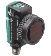
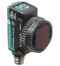
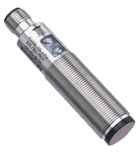
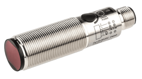
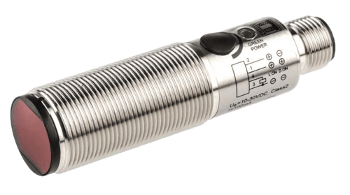
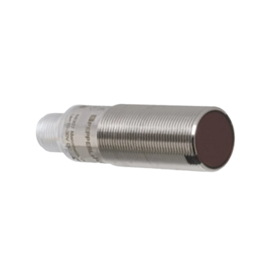
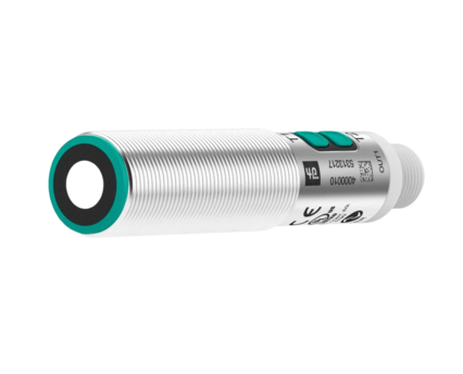
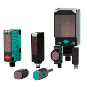
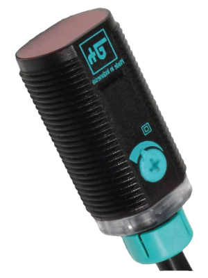
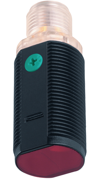
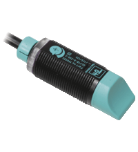
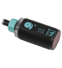
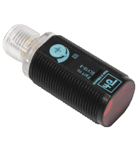
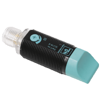
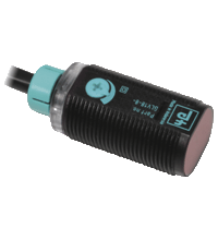
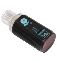
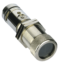
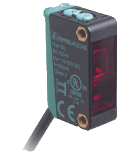
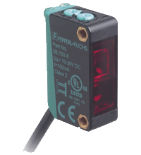
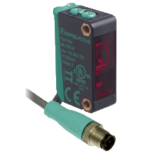
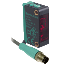
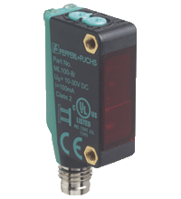
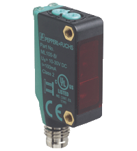
Pepperl+Fuchs Diffuse Mode Sensors
- Miniature design with versatile mounting options
- Extended temperature range
-40?°C ... 60?°C - High degree of protection IP69K
- IO-link interface for service and process data
Diffuse mode sensor OBD800-R103-2EP-IO-V31
- 0 ... 400 mm , adjustable
- 0 ... 25 mm
- 0 ... 400 mm
obd200 18gm60 e5 v1 ir 1c
- LED status indicator
- Reverse polarity protection
- Short-term protection against current overload
- Threaded connection M18 x 1
obd500 18gm60 e5 v1 ir 1c
- Output type: NPN/PNP switching
- Reverse polarity protection: Yes
- Short circuit protection: Yes
- Radiation angle: 360°
obd600 18gm60 e5 v1
- Type: IR LED
- Wavelength: 940 nm
- Working time: > 100,000 hours
uc1000 18gs 2ep io v15
- Degree of protection: IP67
- Ambient temperature: -20...+70 °C
- Body material: PBT
- Efficient Line in a short M18 plastic housing for standard applications
- 4 LEDs indicator for 360?° visibility
- Optimized potentiometer design for a clear control button layout in the application
- Universal usage at different power supplies
glv18 8 200
- Sensor type: non-contact infrared sensor
- Limit supply voltage: 12-24 V DC
- Power consumption: 10 mW
- Operating temperature: -20...+60 °C
- Operating humidity: 5...95 % relative humidity without condensation
glv18 8 450
Delayed switching off: from 0 to 100 ms
Switch-on delay: 0 to 100 ms
Noise filter: 0 to 100 ms
- Efficient Line in a short M18 plastic housing for standard applications
- 4 LEDs indicator for 360?° visibility
- Optimized potentiometer design for a clear control button layout in the application
- Sidelookerversion
- DC voltage version
- Efficient Line in a short M18 plastic housing for standard applications
- 4 LEDs indicator for 360?° visibility
- Optimized potentiometer design for a clear control button layout in the application
- Sidelookerversion
- DC voltage version
- Efficient Line in a short M18 plastic housing for standard applications
- 4 LEDs indicator for 360?° visibility
- Optimized potentiometer design for a clear control button layout in the application
- Version with front optical face
- DC voltage version
- Efficient Line in a short M18 plastic housing for standard applications
- 4 LEDs indicator for 360?° visibility
- Optimized potentiometer design for a clear control button layout in the application
- Version with front optical face
- DC voltage version
- Efficient Line in a short M18 plastic housing for standard applications
- Very high detection range
- 4 LEDs indicator for 360?° visibility
- Optimized potentiometer design for a clear control button layout in the application
- Sidelookerversion
- DC voltage version
- Efficient Line in a short M18 plastic housing for standard applications
- Very high detection range
- 4 LEDs indicator for 360?° visibility
- Optimized potentiometer design for a clear control button layout in the application
- Version with front optical face
- DC voltage version
- Efficient Line in a short M18 plastic housing for standard applications
- Very high detection range
- 4 LEDs indicator for 360?° visibility
- Optimized potentiometer design for a clear control button layout in the application
- Version with front optical face
- DC voltage version
- M30 nickel plated brass threaded housing
- Light/dark switching
- For glass fibre light guide
- Extensive fiber optic product selection as accessories
- Miniature design
- Easy to use
- Very bright, highly visible light spot
- Full metal thread mounting
- Highly visible LEDs for Power ON and switching state
- Not sensitive to ambient light
- Miniature design
- Easy to use
- Very bright, highly visible light spot
- Full metal thread mounting
- Highly visible LEDs for Power ON and switching state
- Not sensitive to ambient light
- Miniature design
- Easy to use
- Very bright, highly visible light spot
- Full metal thread mounting
- Highly visible LEDs for Power ON and switching state
- Not sensitive to ambient light
- Miniature design
- Easy to use
- Very bright, highly visible light spot
- Full metal thread mounting
- Highly visible LEDs for Power ON and switching state
- Not sensitive to ambient light
- Miniature design
- Easy to use
- Very bright, highly visible light spot
- Full metal thread mounting
- Highly visible LEDs for Power ON and switching state
- Not sensitive to ambient light
- Miniature design
- Easy to use
- Very bright, highly visible light spot
- Full metal thread mounting
- Highly visible LEDs for Power ON and switching state
- Not sensitive to ambient light
Pepperl+Fuchs was founded in 1945 by Walter Pepperl and Ludwig Fuchs in Mannheim, Germany. The company is world-renowned in diffuse mode sensors production. We will discuss these devices in more detail below.
Working Principle of Diffuse Mode Sensors
The diffuse sensor uses the principle of reflection to detect objects in the area of effect. The receiver and transmitter are placed in the same housing for diffuse-type sensors. The principle of operation of this device is based on a mirror image. The essence of this process is as follows: the transmitter emits a light beam, which, falling on the object, is scattered in different directions. Some of these waves return to the sensor, hitting the receiver. In this case, the device is activated.
Like any other photoelectric sensor, Diffuse object detection sensors have built-in circuitry for modulating, emitting, receiving, and demodulating the light beam and controlling the output signal. They have an emitter and receiver built into the same package.
A photoelectric sensor, as a rule, has several circuits inside:
- Modulator and amplifier stage. This step generates a signal to turn the LED on and off quickly. The signal is usually in the form of a square wave. The amplifier stage uses the signal from the modulator stage and drives the LED. Some sensors do not have a modulator and output a straight beam. They tend to have a greater range but are more susceptible to interference caused by external light sources.
- Transmitter and receiver. The transmitter is often an LED due to its lower power consumption and switching speed. The emitted light is in the visible light and infrared wavelengths. Red LEDs are the most common type of visible light. A photodiode/phototransistor is used to receive the signal. For a pulsed emitter type, this phototransistor is spectrally related to the wavelength of the emitter LED. This ensures that the phototransistor passes more current when it receives light that falls within the wavelength of the emitter LED.
- Detector amplifier and demodulator stage. The received signal is amplified and further conditioned by filtering and smoothing. The receiver circuitry also works in sync with the transmitter, reducing the chance of external interruptions. This helps the sensor deflect any unwanted light beams emitted at different frequencies directed at the sensor.
- Exit stage. The output stage receives the conditioned signal from the demodulator and switches the output. This can be a source or drain for a PNP/NPN type sensor or simply a normally open or normally closed contact activation for a relay output type sensor.
Advantages of Pepperl+Fuchs Diffuse Mode Sensors
In diffuse sensors, the transmitter and receiver are located in the same housing, allowing you to detect objects using only one component without additional accessories reliably. Thus, diffuse reflection sensors take up little space and can be installed flexibly. They are often used at short distances since the range largely depends on the degree of the detected object's degree of reflection, shape, color, and material properties.
Also, the advantages of such devices include.
- The sensor recognizes all kinds of materials.
- It has a longer service life, extensive sensitivity range, and high reliability.
- Speedy response time and less cost.
- The diffuse photoelectric sensor detects small objects, including the detection of colored marks and labels.
- The reflector-type sensor can detect transparent objects.
- Diffuse mode sensors detection range covers long distances and is resistant to dirty environments.
Applications of Diffuse Mode Sensors
And now, we will look at the most common application areas of diffused sensors.
- Counting small items. In some manufacturing environments, small things fall from a vibrating conveyor into a packaging system or bag, and a photoelectric sensor can count them.
- Color recognition. With independent scanning in red, green, and blue light, with applications across multiple processes in the printing and packaging sectors.
- Monitoring of large areas for objects with light grids. Instead of multiple sensors, the light grid uses parallel beams of light to cover a 2D area.
- Distance measurement. When multiple sensors are used, the triangulation process compares reflected laser beams and can be used to determine position and distance accurately. For example, to check the location of production systems or automated transport applications.
- Logistics and material handling. In automated warehouses with robotic pickers or trucks, position, and object recognition are required for efficient and safe operation.
- Automatic doors. In buildings or public transport, photoelectric sensors detect when someone is standing at the door.
Maintenance of Diffuse Mode Sensors
Like any other type, maintenance of diffuse mode photoelectric sensors is essential to ensure their reliable and accurate performance over time. Proper maintenance practices can help you prevent sensor failures, extend sensor life, and minimize downtime in various applications. Below we will look at a few general tips for maintaining diffuse mode sensors.
- Perform routine visual inspections of the sensor for physical damage, loose connections, or signs of wear. Ensure the sensor lens or transmitter/receiver components are clean and free of dust or debris.
- Keep the sensor lens and optical components clean to maintain optimum performance. Use the appropriate cleaning materials and methods recommended by Pepperl+Fuchs to avoid damaging the sensitive parts of the sensor.
- Some diffuse mode sensors may require periodic calibration to maintain accuracy. Follow the manufacturer's recommendations for calibration intervals and procedures.
- Install the sensor only in a suitable environment for its performance. Factors such as temperature, humidity, and exposure to chemicals or pollutants can affect the device's correct operation.
- Protect the transducer from excessive mechanical impact or shock, which may cause displacement or damage to sensitive components.
- Be sure to route sensor cables correctly to prevent strain on connectors and cables. Avoid sharp bends or kinks in lines and use appropriate cable protection.
- Check electrical connections and terminals regularly to ensure they are secure and free of corrosion or oxidation.
- If the diffuse mode sensor has software or firmware, check for updates provided by Pepperl+Fuchs and apply them as needed to benefit from performance improvements or bug fixes.
- Perform periodic performance tests to check the accuracy and sensitivity of the sensor. Compare the results with the sensor specifications to identify any deviations or problems.
- Always follow the maintenance recommendations provided by the sensor manufacturer in the manual or product documentation. Each sensor model may have specific maintenance requirements.
- Ensure that the personnel responsible for sensor maintenance are appropriately trained in handling, cleaning, and troubleshooting.
- Promptly resolve any failures or anomalies to prevent potential problems from escalating into more severe problems.
