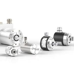
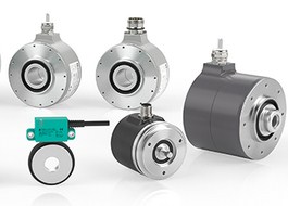
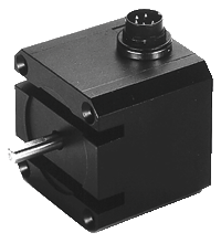
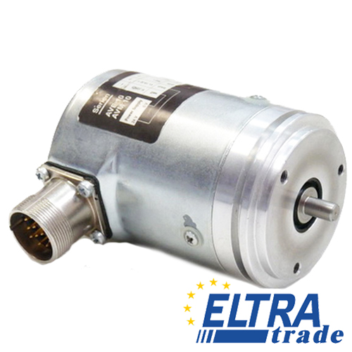
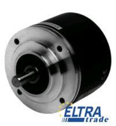
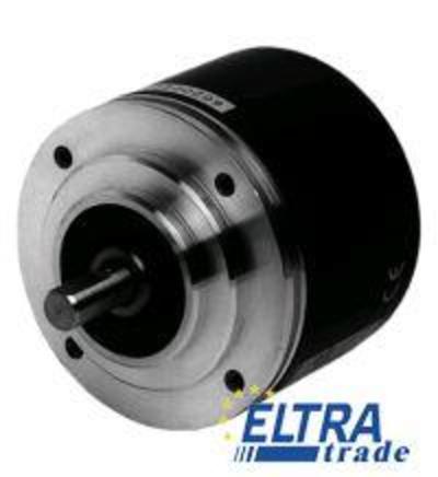
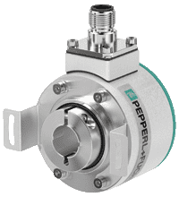
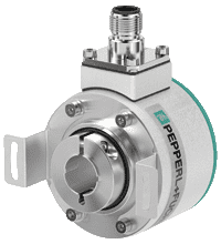
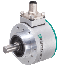
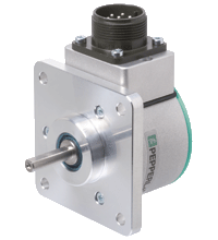
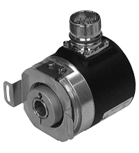
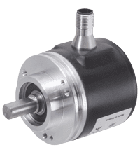
Pepperl+Fuchs Incremental Rotary Encoders
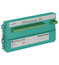
- 12 increased safety outputs (Ex e)
- Short circuit current limitation per output
- Segment Protector in Zone 1/Div. 2
- Instruments in Zone 1/Div. 1
- For FOUNDATION Fieldbus H1 and PROFIBUS PA
- High power on trunk and spurs
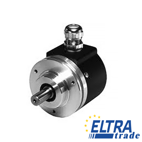
Incremental rotary encoder
ENI58IL S10CA5 1024UD1 RC1
- Shaft torque: Max. 1.5 Nm
- Permissible radial load: Max. 100 N
- Permissible axial load: Max. 50 N
- Impact resistance: Up to 50 g
- Vibration resistance: Up to 10 g (peak-peak)
- Clear function monitoring thanks to LED display (two-coloured)
- Easy installation and control through support functions reduce costs
- Quality assurance through comprehensive self-diagnosis, including coded disc
- Reliable function in the application thanks to internal intelligence during commissioning
- max. 5000
- 140 a
- 20 a
- 1.6 E+9 at 3000 rpm
- Sturdy and compact design
- Up to 2500 ppr
- Rectangular design
- 10 V ... 30 V with short-circuit proof push-pull output
Incremental rotary encoder
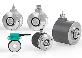
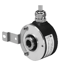
- Housing empty- 58 mm
- Hollow shaft
- Up to 5000 ppr
- Universal output driver
- BlueBeam technology for ultimate precision
- Housing empty- 58 mm
- Recessed hollow shaft
- Up to 5000 ppr
- Universal output driver
- BlueBeam technology for ultimate precision
- Housing empty- 58 mm
- Solid shaft
- Servo or clamping flange
- Up to 5000 ppr
- Universal output driver
- BlueBeam technology for ultimate precision
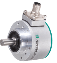
- Housing empty- 58 mm
- Solid shaft
- Square flange
- Up to 5000 ppr
- Universal output driver
- BlueBeam technology for ultimate precision
- Housing empty- 58 mm
- Solid shaft
- Servo or clamping flange
- Universal output driver
- BlueBeam technology for ultimate precision
- Housing empty- 58 mm
- Recessed hollow shaft
- Puls count configurable from 1 ... 16384
- Direction of rotation configurable
- Output type configurable
- Housing empty- 58 mm
- Solid shaft
- Servo flange, square flange or clamping flange
- Puls count configurable from 1 ... 16384
- Direction of rotation configurable
- Output type configurable
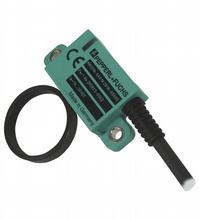
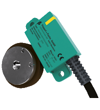
- Cost-effective, bearing-free rotary encoder for rotational speed measurement
- Simple installation
- Operating display verifies function
- High degree of protection (IP67)
- Magnetic ring with 50 poles
- Clear function verification via two-color LEDs (red/green)
- Simple installation and adjustment using assistance functions reduce costs
- Self-diagnostics including the magnetic wheel provide quality assurance
- Internal intelligence provides easy setup and reliable operation
- The elastomer coating of the magnetic wheel provides resistance to dirt as well as thermal and mechanical shock
- Long service life at high speeds and temperatures
- Industrial standard housing &empty-58 mm
- Up to 50,000 ppr
- Hollow shaft
- 10 V ... 30 V with RS 422 interface
- Up to 5000 ppr
Understanding Incremental Rotary Encoders
Incremental rotary encoders are devices used to measure the position or angular displacement of a rotating shaft. Pepperl+Fuchs, being a leading manufacturer of industrial sensors, offers a range of incremental rotary encoders.
Pepperl Fuchs produce the wide nomenclature of encoders, among which it is always possible to find suitable for any industry. In automation encoders are used to measure the angle, rotation, velocity, and acceleration of rotation. Linear motion also can be measured by using spindles, gear racks, measuring wheels or cable mechanisms.
Rotary Encoders convert rotational motion into electrical signals that are processed by counters, tachometers, controllers or computers.
The P+F company offers absolute and incremental rotary encoders with accessories and cable pulls.
Incremental encoders induce only move when driving. They generate output pulses which are counted by the reversible counter therefore, their meter readings correspond to how far the disk has moved from the start. Here basically are used two sensitive elements, located in the transducers so that their outputs are shifted relative to each other by 90° on a phase. In this case it is possible to use special logic to determine the direction and therefore to determine up or down should be considered counter.
Technical Specifications and Features
Encoders typically operate within a specified voltage range. Common voltage ranges include 5V DC or 24V DC. Common output signal types for incremental encoders are TTL (Transistor-Transistor Logic) or HTL (High Threshold Logic). Incremental rotary encoders comply with industry standards or certifications, such as CE, UL, or ATEX for hazardous environments. Below are features of Pepperl+Fuchs incremental rotary encoders
Incremental encoding
Incremental rotary encoders generate a series of pulses as the shaft rotates. These pulses are used to determine the position, speed, and direction of rotation.
Resolution
Resolution refers to the number of pulses per revolution. Higher resolution encoders provide more precise position information. Pepperl+Fuchs encoders may offer a range of resolutions to meet different application requirements.
Output types
Encoders typically provide various output types, such as A, B, and Z channels. The A and B channels provide quadrature signals, while the Z channel (index or reference) provides a signal for a specific position in the rotation cycle.
Hollow shaft or solid shaft
Depending on the application, encoders may come with either a hollow or solid shaft. Hollow shaft encoders are designed to be mounted directly onto the shaft being measured.
Operating temperature range
Encoders are often specified to operate within a certain temperature range. This information is crucial for applications in environments with extreme temperatures.
Shaft load capacity
The maximum permissible axial and radial loads on the shaft can affect the selection of an encoder for a particular application.
Protection ratings
Encoders may have different protection ratings against environmental factors such as dust and water. Common IP (Ingress Protection) ratings include IP65, IP66, or higher.
Diagnostics and monitoring
Some encoders may include diagnostic features, such as built-in monitoring of signal quality or error detection.
Applications in Industrial Motion Control
Let’s find out some common applications where incremental shaft rotary encoders are used in industrial motion control.
Position control
Incremental rotary encoders are extensively used to provide accurate position feedback in various industrial machines, such as CNC machines, robotic arms, and conveyor systems. The encoder signals enable the control system to determine the exact position of moving parts, ensuring precision in manufacturing processes.
Speed control
Industrial processes often require precise control of motor speed. Incremental encoders provide real-time feedback on rotational speed, allowing control systems to adjust motor speed as needed. This is crucial in applications like metal cutting, material handling, and printing.
Automated guided vehicles (AGVs)
AGVs used in warehouses and manufacturing facilities rely on incremental rotary encoders for accurate position feedback. Encoders help AGVs navigate through predefined paths, avoid obstacles, and maintain proper alignment during material transportation.
Printing and packaging
In the printing and packaging industries, where precise registration and synchronization are essential, incremental rotary encoders are used to monitor the position and speed of rollers, print heads, and other moving components. This ensures accurate printing and packaging processes.
Textile machinery
Textile manufacturing involves complex machinery with rotating components. Incremental encoders are employed to monitor the speed and position of spindles, rollers, and other moving parts, contributing to the overall efficiency of textile production.
Metalworking machines
In metalworking applications, such as milling machines and lathes, incremental encoders provide feedback on the position of cutting tools and workpieces. This information is crucial for achieving precision in metal shaping and machining processes.
Material handling systems
Conveyor systems and material handling equipment in warehouses and distribution centers utilize incremental rotary encoders to control the movement and positioning of goods. This ensures smooth and efficient material flow.
Renewable energy
In wind turbines and solar tracking systems, incremental rotary encoders play a key role in tracking the position of blades or solar panels. This allows for optimal orientation to capture wind or sunlight, maximizing energy production.
The pulp and paper industry
In paper manufacturing, where precision is critical, incremental encoders are used in various stages of the production process, including cutting, winding, and printing.
Calibration and Maintenance Procedures
Below are general encoder maintenance guidelines that can help you with the calibration, and maintenance of your devices.
- Follow the manufacturer's installation guidelines to ensure proper mounting and alignment of the encoder.
- Connect the encoder to the appropriate control or readout device as specified in the documentation.
- Configure incremental rotary encoders and set the desired resolution based on the application requirements. Many incremental encoders allow users to adjust the resolution according to the precision needed.
- Verify the encoder's output by manually rotating the shaft and checking the readings. Use the recommended tools or software provided by Pepperl+Fuchs for monitoring.
- Perform visual inspections of the encoder for any signs of damage, contamination, or wear. Address any issues promptly.
- Keep the encoder clean from dust, debris, or other contaminants. Use a gentle, non-abrasive method such as compressed air or a soft brush for cleaning.
- Ensure that the environmental conditions (temperature, humidity, etc.) are within the specified operating range.
- Check for any loose screws or connectors and tighten them as necessary.
- If specified in the documentation, lubricate moving parts according to the manufacturer's recommendations.
- Periodically check the electrical connections to ensure they are secure and free of corrosion.
- Regularly test the encoder's performance using appropriate tools or software. Compare the readings to the expected values to detect any deviations.
Selecting the Right Encoder for Your Motion Control Needs
When selecting the right Pepperl+Fuchs incremental rotary encoder technology for your motion control needs ensure compatibility with your application requirements. Here are some bits of advice to consider.
Resolution
The resolution of incremental rotary encoders determines the precision of the position feedback. Higher resolutions provide finer position control. Consider the required level of accuracy for your motion control system.
Encoder type
Pepperl+Fuchs offers various types of incremental rotary encoders, including optical and magnetic encoders. Optical encoders are known for high precision, while magnetic encoders may offer advantages in certain environments. Choose the type that best suits your application.
Environmental conditions
Consider the operating environment of your motion control system. If the encoder will be exposed to dust, moisture, or extreme temperatures, choose an encoder with the appropriate IP (Ingress Protection) rating and temperature specifications.
Shaft size and mounting
Ensure that the encoder's shaft size and mounting options are compatible with your mechanical setup. Pepperl+Fuchs provides encoders with various shaft sizes and mounting configurations to fit different applications.
Output signal type
Incremental encoders typically produce square wave signals (A, B, and sometimes Z channels). Verify that the output signal type is compatible with your motion controller or drive. Common output types include TTL, HTL, and open collector.
Electrical interface
Check the electrical interface requirements of your motion control system. Pepperl+Fuchs encoders may have different voltage levels, so ensure compatibility with your control electronics.
Speed and frequency
Consider the maximum speed and frequency at which the encoder will operate. Choose an encoder with a speed rating that exceeds the maximum speed of your application to ensure reliable performance.
Commutation (for motor control)
If the encoder is used in motor control applications, check whether it supports commutation signals for brushless motors. Some encoders are specifically designed for motor feedback and commutation.
Compatibility with the control system
Ensure that the chosen encoder is compatible with your overall control system. Check if it supports the communication protocols used by your motion controller or PLC.
