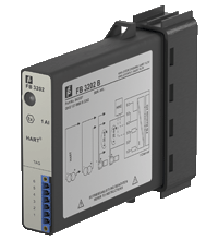
Pepperl+Fuchs FB3202B2
HART Transmitter Power Supply, Input Isolator
We ship
to United States of America
- 1-channel
- Input Ex ia
- Power supply for 2- or 3-wire transmitters with 4 mA ... 20 mA
- Module can be exchanged under voltage (hot swap)
- Installation in suitable enclosures in Zone 1
- Supply circuit 15 V (20 mA)
- Input from active signals of 4-wire transmitters
- HART communication via field bus or service bus
- HART communication also for separately powered devices
- Simulation mode for service operations (forcing)
- Line fault detection (LFD) and Live Zero monitoring
- Permanently self-monitoring
Item Number:
FB3202B2
Delivery standard: 3-6 weeks, depending on the country.
Condition:
new
Contact our experts
- Overview +
- Comments +
| Supplementary information | EC-Type Examination Certificate, Statement of Conformity, Declaration of Conformity, Attestation of Conformity and instructions have to be observed where applicable. For information see www.pepperl-fuchs.com. |
| Transmitter supply voltage | min. 15 V at 20 mA ; 21.5 V at 4 mA |
| LED indication | Power LED (P) green: supply Diagnostic LED (I) red: module fault , red flashing: communication error , white: fixed parameter set (parameters from com unit are ignored) , white flashing: requests parameters from com unit Status LED (1) red: line fault (lead breakage or short circuit) Status LED (2) yellow: Live Zero monitoring |
| Input resistance | 15 Ω (terminals 5, 6) 236 Ω (terminals 1, 6) HART |
| Power consumption | 1.1 W |
| Degree of protection | IEC 60529:2000 |
| INMETRO | Brazil: T??V 14.1596X |
| System information | The module has to be mounted in appropriate backplanes and housings (FB92**) in Zone 1, 2, 21, 22 or outside hazardous areas (gas or dust). Here, observe the corresponding EC-type examination certificate. |
| Power dissipation | 0.75 W |
| Storage temperature | -25 ... 85 ?°C (-13 ... 185 ?°F) |
| HART secondary variable | yes |
| Electromagnetic compatibility | NE 21:2007 |
| Connection | 2-wire transmitter (HART): supply circuit: 2/3+, 4/5- 3-wire transmitter (HART): supply circuit: 2/3+, 6- measuring circuit: 4/5+, 6- 4-wire transmitter (separately powered): measuring circuit: 4/5+, 6- HART measuring circuit: 1+, 6- |
| Shock resistance | shock type I, shock duration 11 ms, shock amplitude 15 g, number of shocks 18 |
| Dimensions | 28 x 107 x 132 mm (1.1 x 4.2 x 5.2 inch) |
| EU-Type Examination Certificate | BVS 13 ATEX E 050 X |
| Resolution | 12 Bit (0 ... 26 mA) |
| Degree of protection | IP20 (module) , a separate housing is required acc. to the system description |
| Number of channels | 1 |
| Ambient temperature | -20 ... 60 ?°C (-4 ... 140 ?°F) |
| Damaging gas | EN 60068-2-42:2003 |
| HART communication | yes |
| Occupied slots | 1 |
| Relative humidity | EN 60068-2-78:2001 |
| Mass | approx. 350 g |
| Vibration resistance | frequency range 10 ... 150 Hz; transition frequency: 57.56 Hz, amplitude/acceleration ?± 0.075 mm/1 g; 10 cycles frequency range 5 ... 100 Hz; transition frequency: 13.2 Hz amplitude/acceleration ?± 1 mm/0.7 g; 90 minutes at each resonance |
| Coding | optional mechanical coding via front socket |
| Line fault detection | can be switched on/off for each channel via configuration tool , configurable via configuration tool |
| Refresh time | 100 ms |
| Connection | backplane bus |
| Environmental test | EN 60068-2-14:2009 |
| Vibration resistance | EN 60068-2-6:2008 |
| Relative humidity | 95 % non-condensing |
| Interface | manufacturer-specific bus to standard com unit |
| Connection | backplane bus |
| Connection | removable front connector with screw flange (accessory) wiring connection via spring terminals (0.14 ... 1.5 mm2) or screw terminals (0.08 ... 1.5 mm2) |
| ATEX approval | BVS 13 ATEX E 050 X |
| Damaging gas | designed for operation in environmental conditions acc. to ISA-S71.04-1985, severity level G3 |
| Rated voltage | 12 V DC , only in connection with the power supplies FB92** |
| Shock resistance | EN 60068-2-27:2009 |
Buy Pepperl+Fuchs FB3202B2 with the best possible price and delivery terms on eltra-trade.com
eltra-trade.com is an online store of industrial automation equipment. New items of automation products are added every day. Your order can be quickly delivered throughout Europe and around the world. We offer you good value for money. We provide our customers with a very quick response and good conditions. Using our professional services will help you be more competitive in the market and it will save you time.

Comments
No comments yet