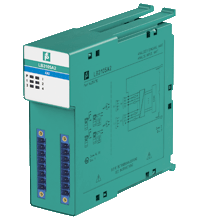
Pepperl+Fuchs LB3105A2
HART Transmitter Power Supply, Input Isolator
- 4-channel
- Inputs Ex ia
- Mounting in Zone 2, Class I/Div.2 or in the safe area
- Power supply for 2-wire transmitters with 4 mA ... 20 mA
- Supply circuit 15 V (20 mA)
- Input from active signals of 4-wire transmitters
- HART communication via field bus or service bus
- Simulation mode for service operations (forcing)
- Line fault detection (LFD): one LED per channel
- Permanently self-monitoring
- Module can be exchanged under voltage
- Overview +
- Comments +
Measurement loop: channel I 3+, 4-, channel II 7+, 8-, channel III 11+, 12-, channel IV 15+, 16-Supply circuit: channel I 1+, 4-, channel II 5+, 8-, channel III 9+, 12-, channel IV 13+, 16-4-wire transmitter (powered externally):Measurement loop: channel I 3+, 4-, channel II 7+, 8-, channel III 11+, 12-, channel IV 15+, 16-3-wire transmitter:Supply circuit: channel I 1+, 2-, channel II 5+, 6-, channel III 9+, 10-, channel IV 13+, 14-
| HART secondary variable | no | ||||||||||||||||||||||||||||||||||
| Rated voltage | 12 V DC , only in connection with the power supplies LB9*** | ||||||||||||||||||||||||||||||||||
| Relative humidity | 95 % non-condensing | ||||||||||||||||||||||||||||||||||
| Damaging gas | EN 60068-2-42:2003 | ||||||||||||||||||||||||||||||||||
| Connection | removable front connector with screw flange (accessory) wiring connection via spring terminals (0.14 ... 1.5 mm2) or screw terminals (0.08 ... 1.5 mm2) | ||||||||||||||||||||||||||||||||||
| Ambient temperature | -20 ... 60 ?°C (-4 ... 140 ?°F) | ||||||||||||||||||||||||||||||||||
| Line fault detection | can be switched on/off for each channel via configuration tool , configurable via configuration tool | ||||||||||||||||||||||||||||||||||
| Electromagnetic compatibility | NE 21:2007 | ||||||||||||||||||||||||||||||||||
| Connection | 2-wire transmitter (HART): | Supplementary information | EC-Type Examination Certificate, Statement of Conformity, Declaration of Conformity, Attestation of Conformity and instructions have to be observed where applicable. For information see www.pepperl-fuchs.com. | Occupied slots | 2 | Damaging gas | designed for operation in environmental conditions acc. to ISA-S71.04-1985, severity level G3 | EU-Type Examination Certificate | BVS 12 ATEX E 024 X | UL approval | E106378 | ||||||||||||||||||||||||
| Environmental test | EN 60068-2-14:2009 | ||||||||||||||||||||||||||||||||||
| Connection | backplane bus | ||||||||||||||||||||||||||||||||||
| Coding | optional mechanical coding via front socket | ||||||||||||||||||||||||||||||||||
| LED indication | Power LED (P) green: supply Diagnostic LED (I) red: module fault , red flashing: communication error , white: fixed parameter set (parameters from com unit are ignored) , white flashing: requests parameters from com unit Status LED (1-4) red: line fault (lead breakage or short circuit) | ||||||||||||||||||||||||||||||||||
| Number of channels | 4 | ||||||||||||||||||||||||||||||||||
| Input resistance | 15 andOmega; | ||||||||||||||||||||||||||||||||||
| Dimensions | 32.5 x 100 x 102 mm (1.28 x 3.9 x 4 inch) | ||||||||||||||||||||||||||||||||||
| HART communication | yes | ||||||||||||||||||||||||||||||||||
| Transmitter supply voltage | min. 15 V at 20 mA ; 21.5 V at 4 mA | ||||||||||||||||||||||||||||||||||
| Vibration resistance | frequency range 10 ... 150 Hz; transition frequency: 57.56 Hz, amplitude/acceleration ?± 0.075 mm/1 g; 10 cycles frequency range 5 ... 100 Hz; transition frequency: 13.2 Hz amplitude/acceleration ?± 1 mm/0.7 g; 90 minutes at each resonance | ||||||||||||||||||||||||||||||||||
| Resolution | 12 Bit (0 ... 26 mA) | Shock resistance | shock type I, shock duration 11 ms, shock amplitude 15 g, number of shocks 18 | Shock resistance | EN 60068-2-27:2009 | System information | The module has to be mounted in appropriate backplanes (LB9***) in Zone 2 or outside hazardous areas. Here, observe the corresponding declaration of conformity. For use in hazardous areas (e. g. Zone 2, Zone 22 or Div. 2) the module must be installed in an appropriate enclosure. | Refresh time | 100 ms | Conversion time | max. 100 ms | Interface | manufacturer-specific bus to standard com unit | Storage temperature | -25 ... 85 ?°C (-13 ... 185 ?°F) | Relative humidity | EN 60068-2-78:2001 | Connection | backplane bus | Vibration resistance | EN 60068-2-6:2008 | Mass | approx. 150 g | Degree of protection | IP20 when mounted on backplane | Power dissipation | 1.5 W | Power consumption | 2.7 W | ATEX approval | BVS 12 ATEX E 024 X | Degree of protection | IEC 60529:2000 | IECEx approval | BVS 12.0055X |
Buy Pepperl+Fuchs LB3105A2 with the best possible price and delivery terms on eltra-trade.com
Find the industrial control components you need at eltra-trade.com. Our catalog offers a variety of sizes and types, all available for prompt delivery. Enjoy competitive pricing and excellent customer service. Trust us to fulfill your automation equipment requirements efficiently and reliably.
Comments
No comments yet