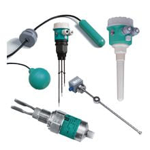
Pepperl+Fuchs LKL-P*
Conductive Level Limit Switch
We ship
to United States of America
- Level limit switch for conductive liquids
- Detect up to five level limits with one probe
- Flexible instrumentation
- No moving parts in the tank
- No calibration: quick and low-cost start up
- Option between rod or rope version for optimum adaptation to the application
- Two-point control and additional maximum and minimum detection
- Approval as overfill protection and leak detection system acc. to WHG
Item Number:
LKL-P*
Delivery standard: 3-6 weeks, depending on the country.
Condition:
new
Contact our experts
- Overview +
- Comments +
| Signal on alarm | output N1 (FEW58): output signal with damaged sensor < 1 mA | ||||||||||||||||||||||||||||||||||||||||||||||||||||
| Influence of ambient temperature | < 0.05 %/K | ||||||||||||||||||||||||||||||||||||||||||||||||||||
| Electromagnetic compatibility | NE 21 | ||||||||||||||||||||||||||||||||||||||||||||||||||||
| Display elements | separate instrument version: dependent on the connected switching unit compact instrument version: output E5 (FEW52), WA (FEW54): - one red light emitting diode: fault message, switching status - one green light emitting diode: operation output N1 (FEW58): - one yellow light emitting diode: fault message, switching status - one green light emitting diode: operation | Current consumption | Output E5 (FEW52): I < 25 mA (without load) output WA (FEW54): 60 mA | Material | probes: - rods: rod 1.4404/316L, insulation: PP - ropes: rope 1.4571/316Ti, insulation FEP, weight 1.4435/316L housing: - output NA (separate instrument version): housing PPS, cover PBT - output E5/WA/N1 (compact instrument version): housing PBT, cover PBT, adapter PBT process connections: PPS | Contact loading | output WA (FEW54): 253 V AC/4 A, 30 V DC/4 A, 150 V/ 0.2 A | Supplementary documentation | technical information TI375O operating instructions KA203O (LKL-P* without electronic insert) operating instructions KA204O (LKL-P* with integrated electronic insert) safety information SI230O (T??V 03 ATEX 2295) safety information SI226O ( approval ZE043O overspill protection acc. to WHG (Z-65.13-378) approval ZE257O leak detection system (Z-65.40-379) | Equipment architecture | probe with integrated electronic insert (compact instrument version) probe without integrated electronic insert (separate instrument version) for one, two or multiple point detection respectively, see section measuring system | Degree of protection | IP66 | Load | Output E5 (FEW52): The load is switched via a transistor (PNP), cycled overload and short-circuit protection, continuous 200 mA (short-circuit proof), residual voltage at transistor at Imax 2.9 V Output WA (FEW54): Loads are switched via 2 potential-free change-over contacts. I~ max. 4 A, U~ max. 253 V P~ max. 1000 VA, cos andphi; = 1, P~ max. 700 VA, cos andphi; > 0.7 I- max. 4 A to 30 V, I- max. 0.2 A to 150 V When connecting a functional extra-low voltage circuit with double insulation in accordance with IEC 1010: The sum of the relay output and power supply voltages is max. 300 V. output N1 (FEW58): refer to datasheet of the connected switch amplifier acc. to IEC 60947-5-6 (NAMUR) | Fail-safe mode | Selecting the correct fail-safe mode ensures that the relay/the output always runs in quiescent current fail-safe. output E5 (FEW52): - maximum fail-safe: The output signal is < 1 mA if the switch point is exceeded (probe covered), a fault occurs or the power supply fails. - minimum fail-safe: The output signal is < 1 mA if the switch point is undershot (probe uncovered), a fault occurs or the power supply fails. Output WA (FEW54): - maximum fail-safe: The relay de-energises when the switch point is exceeded (probe covered), a fault occurs or the power supply fails. - minimum fail-safe: The relay de-energizes when the switch point is undershot (probe uncovered), a fault occurs or the power supply fails. output N1 (FEW58): - maximum fail-safe: The output voltage is 0 V if the switch point is exceeded (probe covered), a fault occurs or the power supply fails. - minimum fail-safe: The output voltage is 0 V if the switch point is undershot (probe uncovered), a fault occurs or the power supply fails. | Mass | separate instrument version: - rod, 1 m (3 ft) long, LKL-P1 with 2, 3 or 5 rods: 415 g, 530 g, 760 g - rope, 1 m (3 ft) long, LKL-P2 with 2, 3 or 5 ropes: 390 g, 470 g, 640 g compact instrument version: - rod, 1 m (3 ft) long, LKL-P1 with 2 or 3 rods (600 g/720 g) - rope, 1 m (3 ft) long, LKL-P2 with 2 or 3 ropes (710 g/800 g) | Supplementary information | EC-Type Examination Certificate, Statement of Conformity, Declaration of Conformity, Attestation of Conformity and instructions have to be observed where applicable. For information see www.pepperl-fuchs.com. | Control elements | - one DIL switch for min/max position - one DIL switch for 0 s or 2 s switching delay - two DIL switches for setting the measuring ranges 100 andOmega;, 1 kandOmega;, 10 kandOmega;, 100 kandOmega; | Process connection | - cylindrical thread G1??A to DIN ISO 228/1 - conical thread 1?? NPT to ANSI B 1.20.1 | Hysteresis | -10 % for the max probe, in reference to the switch point, andDelta;s function deactivated | Overspill protection | see approval (ZE) | Vibration resistance | EN 60068-2-64 | Measurement range | A total of four measuring ranges (100 andOmega;, 1 kandOmega;, 10 kandOmega;, 100 kandOmega;) can be set via two DIL switches (SENS). The setting on delivery is 100 kandOmega;. | Probe | rod probes: compact instrument version 2 or 3 rods, separate instrument version 2, 3 or 5 rods - diameter without insulation: ?events corrosion of the probes and electrolytic destruction of the product. The material used for the tank walls is not important for measurement because the system is designed as a closed potential-free circuit between the probes and the electronics. There is absolutely no danger if the probes are touched during operation. | Input signal | probes covered - A measurable current is flowing between the probes. probes uncovered - There is no measurable current flowing between the probes. | Supply voltage | Output E5 (FEW52): supply voltage 10.8 ... 45 V DC load connection: open collector; PNP switching voltage: max. 45 V Output WA (FEW54): supply voltage 20 ... 55 V DC or 20 ... 253 V AC, 50/60 Hz peak inrush current: max. 2 A, max. 400 ?µs output: two potential-free change-over contacts output N1 (FEW58): refer to datasheet of the connected switch amplifier acc. to IEC 60947-5-6 (NAMUR) | EU-Type Examination Certificate | T??V 03 ATEX 2295 | Non-repeatability | ?± 5 % at 0.1 ... 100 kandOmega; ?± 1 % at 1 ... 10 kandOmega; | Switching time | < 3 s | Switching delay | A switching delay of 2.0 s can be activated or deactivated via a DIL switch. If the switching delay is set to 0 s, the device switches after approx. 0.3 s. | Dimensions | LKL-P1: - housing: max. ?PEPPERL+FUCHS/Explosion Protection/Level Measurement;LMC-Ex;0.00;pepperl-fuchs-lmc-ex;0;0;Pepperl+Fuchs;;;;;;Magnetic Immersion Probe for Continuous Measurement;;
| Degree of protection | IEC 60529:2000 | Optional accessories | LML-FS1 float, ball, ?PEPPERL+FUCHS/Explosion Protection/Level Measurement |
Buy Pepperl+Fuchs LKL-P* with the best possible price and delivery terms on eltra-trade.com
Eltra Trade s.r.o. provides complete industrial automation solutions. With a wide selection of products and efficient delivery options, we meet your needs effectively. Our focus on quality and customer satisfaction distinguishes us. Experience our exceptional service and support for your automation needs.
Comments
No comments yet