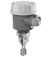
Pepperl+Fuchs LVL-M1
Vibration Limit Switch
We ship
to United States of America
- Limit switch for liquids
- Large selection of process connections: universal use
- Wide variety of electronic modules (e. g., relay, thyristor signal output): the right connection for every process control system
- No calibration: quick and low-cost start up
- No mechanically moving parts: maintenance-free, no wear, long operating life
- Monitoring of the vibrating fork for damage: guaranteed function
- PROFIBUS PA protocol: commissioning and maintenance quick and easy
- Up to SIL 2 acc. to IEC 61508
Item Number:
LVL-M1
Delivery standard: 3-6 weeks, depending on the country.
Condition:
new
Contact our experts
- Overview +
- Comments +
| Climate class | DIN EN 60068-2-38/IEC 68-2-38 |
| Surge protection | electronic insert FEL51 (AC), electronic insert FEL52 (E5), electronic insert FEL54 (WA), electronic insert FEL55 (SI): overvoltage category III |
| Switching point | see section switch point |
| Hysteresis | approx. 2 mm |
| EU-Type Examination Certificate | see instruction manuals (SI) |
| Supplementary information | EC-Type Examination Certificate, Statement of Conformity, Declaration of Conformity, Attestation of Conformity and instructions have to be observed where applicable. For information see www.pepperl-fuchs.com. |
| Supplementary documentation | technical information (TI) manuals, brief instructions (BA, KA) instruction manuals (SI) control drawings (ZD) |
| Surface quality | Ra < 3.2 andmicro;m/80 grit: length, spacer, bushings *A, *B, *E |
| Measurement range | depends on mounting point |
| Current consumption | electronic insert FEL52 (E5): max. 15 mA |
| FM approval | see control drawings (ZD) |
| Influence of medium temperature | max. +1.4 ... -2.8 mm (-40 ... 150 В°C (-40 ... 302 В°F)) |
| SIL classification | up to SIL2 acc. to IEC 61508 |
| Vibration resistance | 10 ... 50 Hz, 0.15 mm, 100 cycles |
| Electromagnetic compatibility | NE 21 |
| IECEx approval | see instruction manuals (SI) |
| Process connection | - cylindrical thread G3/4A, G1A to DIN ISO 228/1 with flat seal to DIN 7603 - conical thread R3/4, R1 to DIN 2999, part 1 - conical thread 3/4NPT, 1NPT to ANSI B 1.20.1 - flush-mounted with welding sleeve to factory standard (G3/4A, G1A) - Triclamp 1-1/2 inch, 2 inch to ISO 2852 - flanges to EN 1092-1 from DN25, to ANSI B 16.5 from 1 inch, to JIS B 2238 (RF) from DN25 For further information see type code. |
| Dimensions | housing: diameter max. 85 mm, height max. 173 mm temperature separator, flameproof bushing: additional length L 140 mm process connection: length L 66.5 ... 80 mm extension: length type II, for vertical installation from above same switching point as Vibracon LVL1, LVL2 vibration fork: width 17.5 mm, fork width 10 mm, length 25 mm |
| Function principle | limit detection Maximum or minimum detection in tanks or pipelines containing all types of liquids including use in explosion hazardous areas. Particularly suited to very aggressive liquids thanks to high degree of corrosion protection. |
| Construction type | compact device |
| Material | wetted parts: - process connection: 1.4435/316L or 2.4610/Alloy C4 - vibration fork: 1.4435/316L or 2.4610/Alloy C4 - flat seal for process connection G2* or G3*: elastomer fibre, asbestos-free housings: - polyester housing: PBT-FR with PBT-FR cover or with PA12 cover with sight glass, cover seal: EPDM - stainless steel housing: 1.4435/316L, cover seal: silicone - aluminum housing: EN-AC-AlSi10Mg, plastic-coated, cover seal: EPDM - compact housing with valve connector or M12 connector: 1.4435/316L cable gland: polyamide or brass, nickel-plated temperature spacer: 1.4435/316L flameproof bushing: 1.4435/316L |
| Influence of medium pressure | max. 0 ... -2.5 mm (-1 ... 64 bar) |
| Storage temperature | -50 ... 80 В°C (-58 ... 176 В°F) |
| Maximum measured error | max. В± 1 mm, specified by mounting position |
| Influence of medium density | max. +4.8 ... -3.5 mm (0.5 ... 1.5 g/cm3) |
| Measuring method | The forks of the sensors vibrate at their intrinsic frequency. This frequency is reduced when covered with liquid. The change in frequency then activates the limit switch. |
| Reference operating conditions | ambient temperature: 23 В°C (73.4 В°F), medium temperature: 23 В°C (73.4 В°F), product density: 1 g/cm3 (water), viscosity: 1 mm2/s, medium pressure pe: 0 bar, sensor mounting: vertical from above, density switch: to > 0.7 g/cm3 |
| Rated voltage | electronic insert FEL50A (PA): 9 ... 32 V DC electronic insert FEL51 (AC): 253 V AC, 50/60 Hz electronic insert FEL52 (E5): 10 ... 55 V DC electronic insert FEL54 (WA): 19 ... 253 V AC, 50/60 Hz or 19 ... 55 V DC electronic insert FEL55 (SI): 11 ... 36 V DC, PLC electronic insert FEL56 (N1), FEL58 (N2): isolating amplifier acc. to EN 60947-5-6 (NAMUR) |
| Non-repeatability | 0.1 mm |
| Control elements | electronic insert FEL50A (PA): 8 switches for device address setting electronic inserts FEL51 (AC), FEL52 (E5), FEL54 (WA), FEL55 (SI), FEL56 (N1): two switches for fail-safe mode and density change electronic insert FEL58 (N2): two switches for fail-safe mode and density change and one test button interrupts lead |
| Display elements | electronic inserts: - electronic inserts FEL50 A (PA), FEL58 (N2): green LED, yellow LED - electronic inserts FEL51 (AC), FEL52 (E5), FEL54 (WA), FEL55 (SI), FEL56 (N1): green LED, red LED compact housings: compact housing with valve connector - electronic version FEL51 (AC), FEL52 (E5): green LED, red LED - electronic version FEL58 (N2): green LED, yellow LED compact housing with M12 x 1 round connector without LEDs - electronic version FEL52 (E5): green LED, yellow LED, red LED - electronic version FEL58 (N2): green LED, yellow LED compact housing with M12 x 1 round connector with LEDs - electronic version FEL52 (E5): green LED, two yellow LEDs |
| Function test | compact housing: function test with test magnet electronic versions FEL51 (AC), FEL52 (E5) and FEL58 (N2): During the test, the current state of the electronic switch is reversed. |
| Power consumption | electronic insert FEL52 (E5): max. 0.83 W electronic insert FEL54 (WA): max. 1.3 W |
| Ambient temperature | -50 ... 70 В°C (-58 ... 158 В°F) , function with reduced data values see section ambient temperature |
| Measured variable | limit level (limit value) |
| Mass | 600 g , basic weight: compact sensor, electronic insert, stainless steel housing, process connection G2*, additional weight is dependent on housing and process connection process connections: - A31 1000 g, A41 1200 g, A51 1500 g, A6* 2400 g, A81 4900 g, A91 7000 g - C45 1400 g, C51 1200 g, C71 1600 g, C75 3200 g, C95 5900 g, CA3 5600 g - D45 1400 g, D51 1200 g, D71 1600 g, D75 3200 g, D95 5900 g, DA3 5600 g - F45 1400 g, F51 1200 g, F55 2000 g, F61 1400 g, F65 2400 g, F71 1600 g, F75 3200 g, F7F 2600 g, F81 2400 g, F85 4300 g, F93 4800 g, F95 5900 g, FA3 5600 g, FA5 7500 g - G3* 200 g - J13 no information, J16 no information, J17 1700 g, J19 no information, J1A no information, J1C 1700 g - N3* 200 g, N75 2900 g - R3* 200 g - T51 no information, T61 100 g temperature spacer, flameproof bushing: - IA 600 g, QA 700 g |
| Overspill protection | see approval (ZE) |
| Designation | see technical information (TI) |
| Switch behaviour | switch-over for minimum/maximum residual current safety on electronic insert MAX = maximum safety: The output switches to the power fail response when the fork is covered. for use with overspill protection for example MIN = minimum safety: The output switches to the power fail response when the fork is exposed. for use with dry running protection for example When switching on the power supply the output assumes the alarm signal. After max. 2 s it assumes the correct switching mode. |
| Medium density | adjustment on the electronic insert > 0,5 g/cm3 or > 0,7 g/cm3 (other on request) |
| Degree of protection | IEC 60529 |
| Vibration resistance | EN 60068-2-6 |
| CSA approval | see control drawings (ZD) |
| Switching delay | when fork is covered: approx. 0.5 s, when fork is exposed: approx. 1.0 s (other switching times on request) additionally configurable for PROFIBUS PA (electronic insert FEL50A (PA)): 0.5 ... 60 s |
| Degree of protection | polyester, steel, and aluminum housing: IP66/IP67 compact housing: - IP65 with valve connector PG11 or 1/2NPT - IP66/IP68 with M12 x 1 connector without LEDs (1.4435/316L) - IP69K with M12 x 1 connector with LEDs (1.4435/316L) |
| Connection | electronic inserts: cross section max. 2.5 mm2, lace in end splice in acc. with DIN 46228 ground lead in housing: cross section max. 2.5 mm2 external equipotential bonding: cross section 4 mm2 |
Buy Pepperl+Fuchs LVL-M1 with the best possible price and delivery terms on eltra-trade.com
Eltra Trade s.r.o. offers premium industrial control products. Our vast inventory and express delivery options ensure you receive your order quickly. We prioritize quality and customer satisfaction. Contact us today to learn more about our offerings and how we can assist your business.
Comments
No comments yet