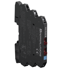
Pepperl+Fuchs M-LB-Ex-2144
Surge Protection Barrier
We ship
to United States of America
- Surge protection barrier for 2 signal lines
- Nominal voltage 24 V DC
- Surge protection barrier for grounded signal lines
- Max. surge current (8/20 µ-s) 20 kA
- Connection via screw terminals
- DIN rail mountable
- Up to SIL 3 acc. to IEC 61508
Item Number:
M-LB-Ex-2144
Delivery standard: 3-6 weeks, depending on the country.
Condition:
new
Contact our experts
- Overview +
- Comments +
| Relative humidity | max. 95 % , without condensation |
| Impulse reset time | < 500 ms |
| Insertion loss | ≤ 3 dB at 0 ... 700 kHz in 100 Ω system |
| Impulse rating | 1 kV/0.5 kA (category C1) 10 kV/5 kA (category C2) 1 kA (category D1) |
| Maximum continuous operating voltage | 30 V DC |
| Mass | approx. 32 g |
| Voltage protection level | max. 45 V line-line for nominal discharge current In max. 60 V line-earth for nominal discharge current In |
| Supplementary information | Observe the certificates, declarations of conformity, instruction manuals, and manuals where applicable. For information see www.pepperl-fuchs.com. |
| Surge protective devices for low voltage | IEC 61643-21:2000+A1:2008+A2:2012 |
| EU-type examination certificate | KIWA 19 ATEX 0003 X |
| Degree of protection | IP20 , after mounting of the insulation spacer |
| Rated current | 500 mA , restrictions see derating characteristics |
| Impulse discharge current (10/350 µs) | 1 kA per line (2x) |
| Safety Integrity Level (SIL) | SIL 3 |
| Material | Polyamide (PA) |
| Total discharge current (8/20 µs) | 20 kA (1x) , overstressed fault mode 3 acc. to IEC 61643-21 |
| Nominal voltage | 24 V DC |
| Leakage current | < 6 µA at 24 V and 25 ?°C (77 ?°F) , line-line |
| Functional safety | IEC/EN 61508:2010 |
| Designation | - insulation spacer M-LB-2800 - terminal block USLKG5 |
| Nominal discharge current (8/20 µs) | 5 kA per line (10x) |
| Connection | screw terminals , max. core cross section 1 x 2.5 mm2 |
| Ambient temperature | -40 ... 80 ?°C (-40 ... 176 ?°F) Observe the temperature range limited by derating, see section derating. |
| Storage temperature | -40 ... 85 ?°C (-40 ... 185 ?°F) |
| Topology | grounded |
| Number of protected signal lines | 2 |
| Connection | protected area: terminals 4, 5 unprotected area: terminals 2, 3 shielding/grounding: terminal 1 (optional) |
| Dimensions | 6.2 x 72.4 x 93 mm |
| Electromagnetic compatibility | EN 61326-3-1:2017 |
| Series resistance | ≤ 3 Ω per line |
| Mounting | on 35 mm DIN mounting rail acc. to EN 60715:2001 |
| Degree of protection | IEC 60529:2013 |
Buy Pepperl+Fuchs M-LB-Ex-2144 with the best possible price and delivery terms on eltra-trade.com
eltra-trade.com is an electrical equipment shop. We have the status of the official representative of many European brands. We deliver to any country in the world. Our company is not an official distributor of all brands, but we can offer you competitive prices for all items in our catalog. We provide accurate delivery time information at the very beginning. We are the partner who can trust.

Comments
No comments yet