How to Diagnose Encoder Feedback Errors in Motion Control Systems
28.05.2026
If the position starts to "float" or the speed readings jump wildly, I don't rush to order a new sensor. In most cases, the problem isn't with the device itself, but with its surroundings. In this guide, I'll explain how to diagnose an encoder feedback error in real-world conditions, when you don't have time to guess and the machine should have been working yesterday. My goal is to show you that diagnostics aren't magic, but a consistent verification of the physics of the process.
Today we'll cover:
What encoder feedback errors look like in real systems;
The most common causes: noise, misalignment, wiring, and resolution mismatch;
How electrical and mechanical issues affect encoder signals;
Why feedback errors lead to instability, positioning issues, and machine faults;
Step-by-step troubleshooting method used in real industrial environments.
What Does an Encoder Feedback Error Look Like?
In my experience, encoders rarely "die" completely. This usually manifests as strange system behavior that's difficult to detect during a routine inspection. You might notice unstable speed readings, with the drive jerking, or constant position drift, with the carriage missing a few millimeters with each cycle. If you see random jumps in data or feel a strange high-frequency vibration in the motor, you're likely experiencing an encoder feedback instability.
The main difficulty is that problems often occur intermittently. Signal noise can easily be confused with mechanical resonance, but there's one clue: mechanical problems are usually constant and depend on the shaft's rotation angle, while electrical problems depend on the load, brake cycles, or the operation of adjacent equipment. Most encoder problems don't manifest as complete failures – at first, they appear as inconsistent behavior, which technicians often attribute to software glitches, and spend weeks rewriting code where they simply need to adjust the cable shield.
The #1 Cause of Encoder Errors – Electrical Noise
If you ask me what most often kills a signal, I'd answer: interference. An industrial plant is full of "dirty" electricity, and encoder signal noise can turn crisp rectangular pulses into an unreadable "saw" or "fence" pattern that a PLC simply can't recognize. This leads to false counter triggering or data loss.
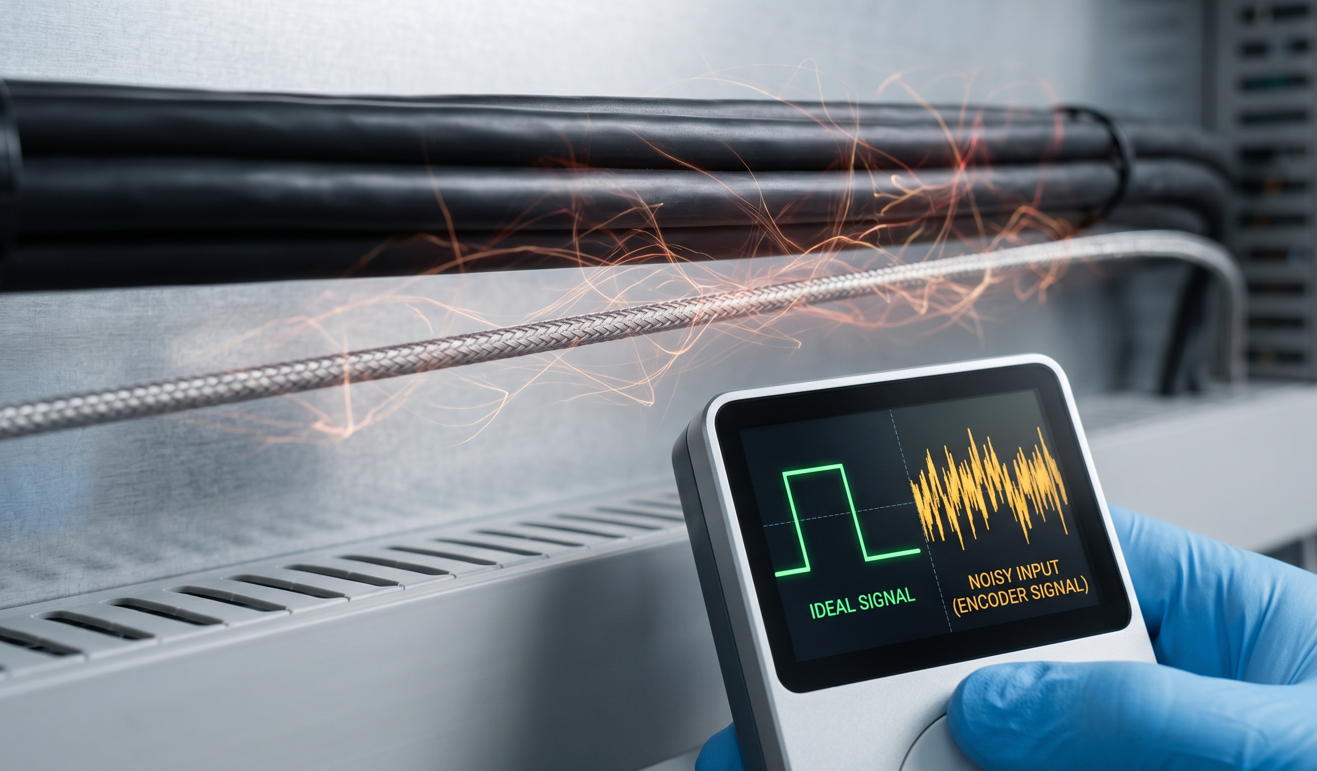
The main sources of problems are VFDs, which generate powerful electromagnetic emissions when switching the motor windings. When the signal wire runs in the same tray as the motor power cable for 20 meters, interference is inevitable. I always start my inspection with a route inspection: I look at how the cables are routed, check the integrity of the shield, and check the quality of the grounding in the cabinet. Remember that interference can come through the air and through the common power bus if the encoder power supply isn't isolated from the control circuits of the high-power contactors. If possible, I monitor the signal with an oscilloscope directly at the controller input – this is the only way to detect any interference that might affect operation.
Mechanical Roots of Feedback Errors
Sometimes engineers get so caught up in searching for interference that they forget a simple truth: an encoder is a mechanical device rigidly connected to the shaft.
- Shaft misalignment
Even a slight misalignment between the encoder shaft and the motor shaft will cause cyclical runout. This introduces fluctuations into the signal and destroys the encoder bearings in a matter of weeks. I always check alignment by touch or with an indicator, as micro-vibrations at high speeds make the feedback unstable, causing a "shaft wobble" effect when the shaft is static.
- Loose coupling or mounting
If the coupling is loose or has internal defects, play appears between the shafts. This causes the encoder to lag when changing direction, creating positioning errors. Vibration from a poorly mounted encoder housing also introduces high-frequency noise into the data, which the control system mistakenly interprets as real movement, causing the servo to constantly steer.
- Bearing wear
Bearing wear in the encoder itself or in the motor introduces mechanical play (axial and radial). This is critical for precision positioning systems, as the shaft begins to "wander" under load, and the optical disk inside the encoder can even begin to interfere with the reading head.
Wiring and Signal Transmission Problems
Sometimes the problem can be solved simply by tightening the terminals. Bad contacts, broken wires inside the cable (especially in cable management systems), or reversed channels A and B are classic encoder troubleshooting. Sometimes the cable is too long, and due to a voltage drop at the other end, the signal becomes too weak for the controller to detect.
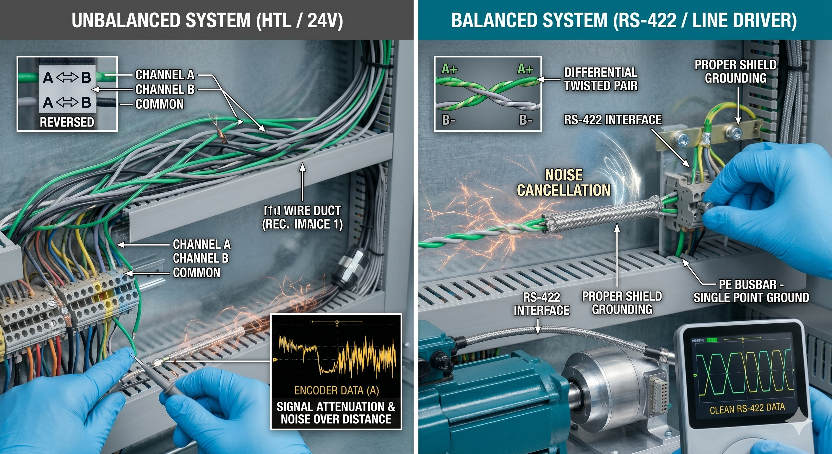
To avoid motion control encoder issues, I always recommend using differential signals (RS-422, Line Driver). Unlike a standard HTL (24V) or Open Collector, a differential signal transmits a pulse and its inversion over a pair of wires. The controller compares the voltage difference between them and effectively rejects external interference that arrives on both wires simultaneously. Proper shielding and grounding of the shield on only one side (usually in the cabinet, on the PE busbar) will eliminate current loops that occur due to potential differences between the machine frame and the ground in the cabinet.
Advanced Diagnostics: Using an Oscilloscope
When the multimeter shows "some volts" and the problem persists, I pull out an oscilloscope. This is the engineer's "eye." When diagnosing encoder pulse loss, I look for the following artifacts:
Ringing and overshoot. If "ringing" is visible at the corners of rectangular pulses, this indicates improper line termination or excessive cable capacitance;
Slow rise times. If, instead of a steep rise, the pulse appears as a gentle hill, the cable is too long for the selected frequency, and the controller simply doesn't have time to register a high voltage;
Common mode noise. If, when the engine is stopped, noise is visible on the signal lines, synchronous with the operation of a nearby high-power pump, there are problems with the shielding or grounding.
Resolution and Configuration Mistakes
Sometimes, the mechanical and electrical components are in good working order, but the system still generates errors. This occurs due to incorrectly configured PPR (pulses per revolution) or CPR parameters in the program. If the resolution in the controller doesn't match the actual resolution of the encoder, you'll get incorrect position scaling and unstable control loop operation.
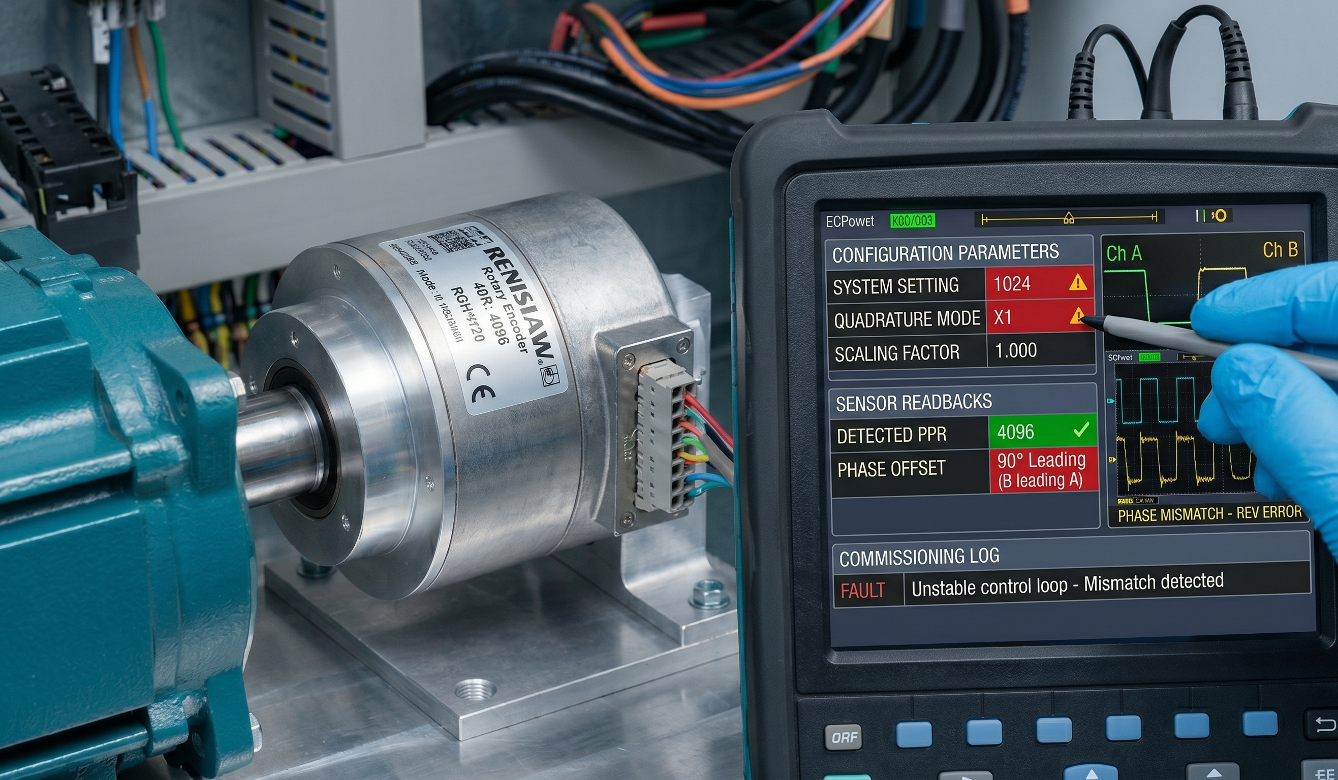
I often encounter PLC encoder troubleshooting problems during the commissioning phase, where the problem was solved simply by changing the scaling factor in the drive settings or adjusting the input type (Quadrature x1, x2, or x4). Phase mismatch (when channel B leads A instead of reversing) causes the controller to think the shaft is rotating in the wrong direction, causing an immediate following error.
Environmental Factors That Cause Errors
Harsh operating conditions such as dust, moisture, vibration, and extreme temperatures will eventually destroy even the most reliable encoder. I've seen condensation inside the encoder housing cause short circuits, and fine metal dust on the optical drive cause pulse skips. Under these conditions, the signal gradually degrades, and it's important to quickly detect when the encoder not reading correctly due to dirty optics. For aggressive environments, I always recommend using encoders with IP67 protection and magnetic sensors over optical ones, as they are much more resistant to oil and dirt.
If you are looking for solutions that can survive these conditions, I highly recommend exploring our catalog of
Step-by-Step Diagnosis (How I Troubleshoot Encoder Issues)
When a machine stalls, I don't rush around the shop floor, but follow a clear plan to conduct effective encoder troubleshooting:
Check symptoms. I analyze what exactly is happening: speed fluctuations (noise), position drift (missed pulses), or the drive crashes only at high speeds (frequency limit);
Verify power supply. I measure the voltage directly at the encoder connector. A drop of even 0.5V can make the logic unstable;
Inspect wiring. I check the tightness of the terminals and the integrity of the shield. I look for places where the encoder cable may intersect with the power wires;
Measure signal. I use an oscilloscope to see the actual shape of the pulses at the PLC input;
Check mechanics. I check the couplings for tightness, play, and shaft radial runout;
Manual test. If possible, I rotate the shaft manually (slow motion) and check whether the PLC diagnostic values change consistently;
Compare counts. I compare the actual actuator movement with the readings on the screen;
Swap the encoder. And only if all physical and electrical factors have been ruled out do I replace the encoder with a new one.
Fixes That Actually Work (Not Just Replacing the Encoder)
You can often find a solution to the problem of how to fix encoder errors without buying new parts. Improving grounding by installing an insulator between the encoder and the motor (to prevent interference from the motor housing from transferring to the encoder housing) is an excellent technique. Rerouting cables away from the VFD or installing ferrite beads on the inverter output cables solves the interference problem in 80% of cases. Also, if the cable is long, I sometimes recommend reducing the load resistance on the controller side to make the signal more robust and resistant to interference.
Preventing Encoder Feedback Errors in New Installations
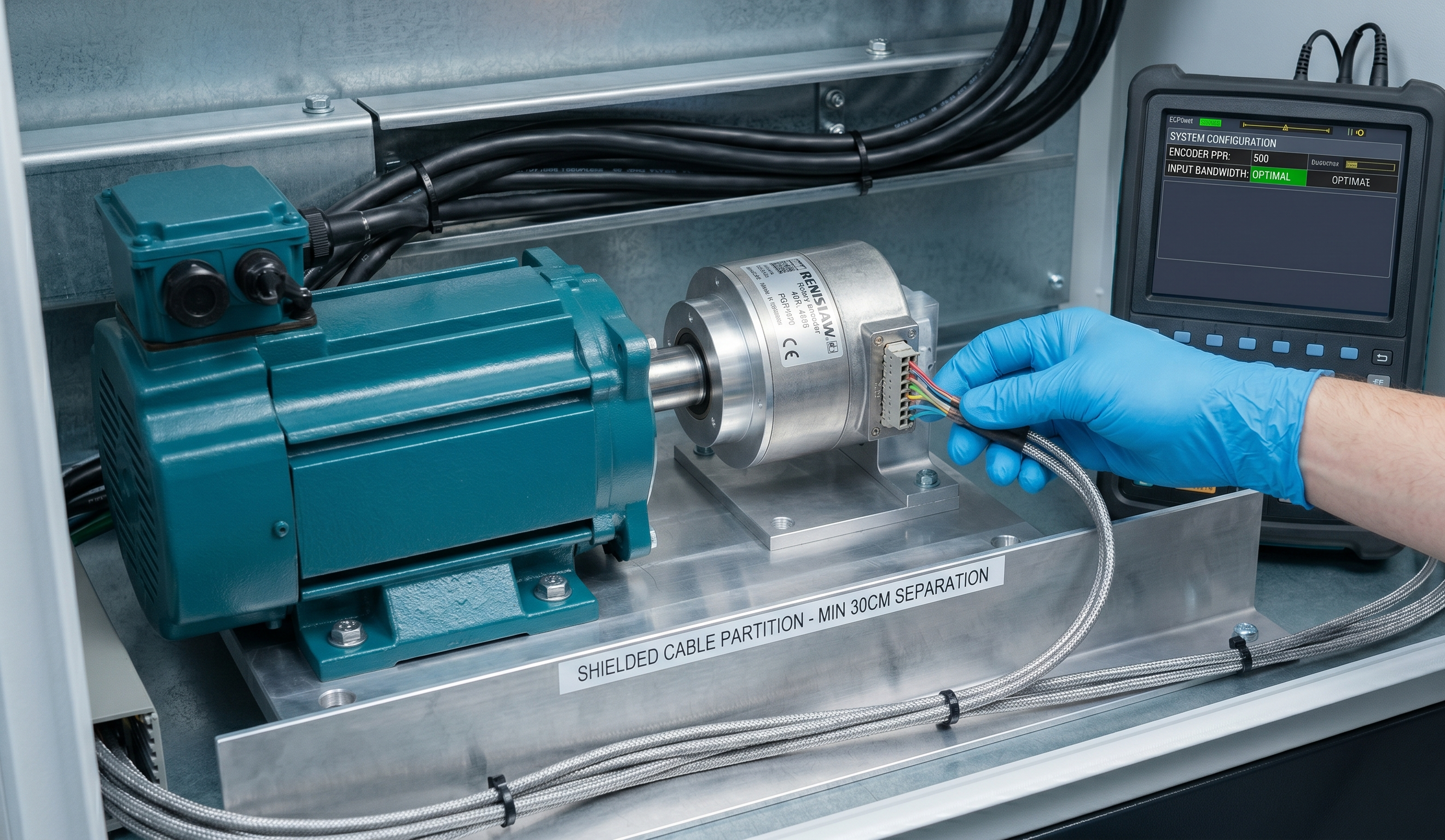
To prevent mistakes, it is important to properly design your project. To do this, I separate the power and signal cables by at least 20-30 cm using either a physical barrier or shielded metallic partitions. In addition, I will typically use high-quality shielded twisted pair cable for my signal lines and will secure my encoders using the manufacturer-recommended mounting method to minimize electrical interference within the encoder’s output. Finally, use a resolution appropriate for your application (e.g., don’t use a 10,000 PPR encoder where a 500 PPR encoder would suffice) to prevent overflow errors from occurring in the PLC and losing encoder pulses from exceeding the input bandwidth.
Real-World Examples from the Field
Over the years, I've collected a whole collection of cases where standard textbook solutions failed, forcing me to look for the root cause:
Conveyor system. Due to noise from the VFD, the system was missing pulses, and the belt was constantly "flying" past the stop mark. We solved the problem by routing the signal and power cables to separate trays and adding ferrite filters to the inverter output;
CNC axis. Constant position drift on the CNC machine was caused by a slight misalignment of the coupling, which created micro-vibrations and disrupted optical disk reading. After precise shaft alignment and replacing the rigid coupling with a bellows coupling, positioning accuracy returned to specifications;
Packaging machine. The cause of erratic feedback errors was a loose M12 connector, which only lost contact during peak frame vibrations. I replaced the damaged connector and secured the cable to a rigid bracket, which eliminated the intermittent signal issue;
Motor feedback. An excessively long cable run without using a differential signal resulted in pulse attenuation, and the PLC simply didn't detect rotation at high speeds. We switched to a Line Driver (RS-422) interface and installed a low-resistance cable, restoring stable data transmission to the controller.
Encoder Error vs Drive/PLC Problem (How to Tell)
It's important to be able to differentiate areas of responsibility. If the feedback fluctuates erratically even when the shaft is stationary, this is a clear sign of encoder signal problems (noise). If the encoder data appears logical and smooth, but the controller displays a mismatch error, the problem lies in the PID controller settings or the drive mechanics (for example, a seized bearing). If the motor hums and vibrates while in place, but the encoder data is stable, the problem should be looked for in the motor's power circuits or the driver's auto-tuning parameters.
FAQs About Encoder Feedback Errors
1. Why is my encoder signal unstable?
Signal instability is usually caused by electromagnetic interference from frequency converters or poor contact in the connectors. I also frequently check the mechanical alignment of the shafts, as vibration can physically break the contact or distort the disk reading.
2. Can electrical noise damage encoder signals?
Interference rarely physically damages the electronics, but it effectively "clogs" the useful signal with false pulses. This causes the controller to see encoder signal noise instead of real data, causing erratic motor behavior.
3. How do I check the encoder wiring?
I start by checking each wire for continuity and checking for short circuits between the phases and the shield. Be sure to connect the cable shield to ground at only one end to avoid parasitic current loops.
4. Why do I get wrong position readings?
Positioning errors are most often related to encoder pulse loss, when the controller misses some pulses due to excessively long cables or interference. It's also worth checking the scaling settings in the PLC to ensure the pulses per revolution (PPR) in the program strictly match the encoder specifications.
5. Should I replace the encoder immediately?
Don't rush into replacing it, as in 80% of cases, the problem lies in the cable, grounding, or mechanical coupling. First, troubleshoot the encoder using my algorithm to avoid wasting money on purchasing a working device.