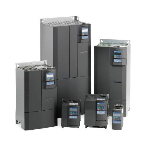
Types of Variable Frequency Drives
26.03.2022
The variable speed drive is designed to control a motor by controlling parameters. The speed is directly proportional to the frequency. Therefore, by varying the frequency, it is possible to maintain the speed of the motor shaft rotation, set according to the technology.
There are three basic types of VFD drives.
- Current inverter drives (CSI) have a long and successful history in signal processing and industrial power equipment.
- Voltage inverter (VSI) based drives have a low power factor, can cause a motor ripple at frequencies below 6 Hz, and do not allow for regeneration.
- Pulse Width Modulated (PWM) drives are the most commonly used drive type due to their excellent input power factor, lack of motor ripple, high efficiency, and lower cost compared to their counterparts.
Technical features of the frequency drive application
- You can freely switch to any mode in the settings to ensure high performance.
- Almost all devices have diagnostic functions so that a malfunction can be corrected quickly. However, it is advisable to check the settings first, to avoid unintentional actions by workers.
- An adjustable actuator can synchronize conveyor processes or set a certain ratio of interdependent quantities. The reduction of the equipment leads to an optimization of the technology.
- In the auto-tuning state, the motor parameters are automatically stored in the inverter memory. This increases the accuracy of the torque calculation and improves the slip compensation.
Frequency converters differ in design, the principle of operation, and the method of control. Let's look at all the types of VFD that are relevant today.
Electro-machine frequency drives
Electro-machine or inductive frequency drives are alternating current motors that are switched to generator mode. These electrical devices are used relatively rarely, in applications where mechanical VFD frequency inverters are difficult or impossible to use.
Electronic frequency drives
Semiconductor frequency drives consist of the power part, based on transistors or thyristors, and control circuitry based on microcontrollers. This electrical equipment is suitable for three-phase and single-phase drives for any purpose. A distinction is made between direct-coupled and DC-link devices.
Direct frequency drives
These frequency drivers are built based on thyristor converters, connected by the bridge, cross, zero, and counter-parallel schemes. Devices of this type are plugged directly into the mains.
Advantages of direct frequency converters:
- The ability to regenerate power to the mains during motor braking operation. The direct connection provides a two-way exchange of electricity.
- High efficiency due to single-frequency conversion.
- Possibility of power increases by the connection of additional converters.
- Large range of low frequencies. Direct inverters provide stable drive operation at low speeds.
Disadvantages of direct frequency inverters:
- An approximated shape of the output voltage with the presence of constant components and subharmonics. This form of AC voltage at the output of the device causes additional heating of the motor, reduces torque, creates interference.
- The frequency of the voltage at the inverter output does not exceed the similar characteristic of the mains voltage. Thus, with these devices, you can only reduce the speed of rotation of motors.
- The main area of direct converters is electric drives based on asynchronous and synchronous motors of high and medium power.
Frequency converters with DC-link
Frequency converters of this type are based on the double conversion circuit. Supply mains voltage is converted to DC, then smoothed and inverted into a variable output voltage of specified frequency.
Advantages of converters with DC intermediate link:
- The ability to produce an output voltage with a frequency either higher or lower than that of the analogous mains supply. Frequency converters based on the double conversion circuit are used for high-medium and low-speed electric drives.
- Pure sinusoidal voltage shape at the output. The converter circuit allows receiving an alternating voltage with the minimum deviation from a sinusoidal form.
- Possibility to build simple and complex power and control circuits for drives with different requirements to the response speed, speed range.
- Adaptability to DC power networks. Inverters of this type can be adapted for power supply from backup and emergency direct current sources without additional devices. This makes it possible to use such frequency converters in drives of critical equipment with backup power sources.
- Variety of control algorithms. DC link converters can be programmed and adapted to almost all-electric drives, including pretentious ones, where particularly precise control of speed and torque is required.
Disadvantages of DC-link converters:
- Relatively large weight and dimensions due to the presence of a rectifier, filter, and inverter unit.
- Increased power losses. The double conversion scheme slightly reduces overall efficiency.
Design of converters with DC-link
Such converters consist of several basic units:
- Rectifier. For PD, diode and thyristor DC converters are used. The first is characterized by the high quality of direct voltage with almost no ripple, low cost, and reliability. However, diode rectifiers do not allow to realize the possibility of power recovery into the network when braking the motor. Rectifiers on thyristors provide the possibility of current flow in both directions and allow disconnecting the converter from the network without additional switching equipment.
- Filters. The output voltage of thyristor-controlled rectifiers has a significant ripple. To smooth it out, reactors, capacitive or inductive-capacitive filters are used.
- Inverters. Voltage and current inverters are used in PDs. The latter provides energy recovery into the network and is used to control electric machines with frequent starting, reversing, and stopping, for example, crane engines.
- Frequency inverters based on voltage inverters produce a pure sine waveform at the output. Because of this, converters of this type are most widely used.
- Microprocessor. This unit controls the input rectifier, receives and processes signals from the sensors, interacts with the higher-level automated system, records and stores information about the events, forms the output voltage of the frequency relevant PD. It also performs the functions of protection against overloads, phase loss, and other emergency and abnormal modes of operation.
Eltra Trade has a wide selection of Variable Frequency Drives at unbeatable prices. Our knowledgeable managers are here to help you choose the right product for your needs, ensuring efficient delivery worldwide.