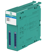
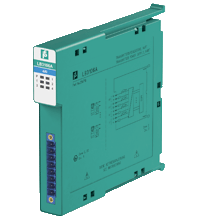
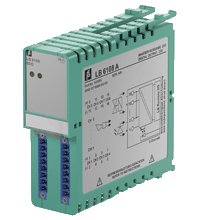
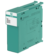
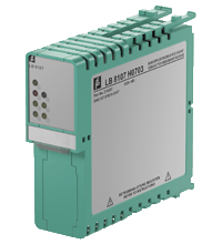
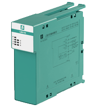
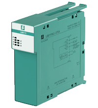
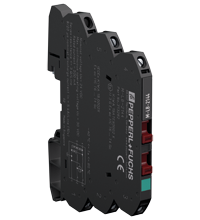
Pepperl+Fuchs Remote IO Systems
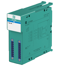
- 8-channel
- Inputs Ex ia
- Mounting in Zone 2, Class I/Div.2 or in the safe area
- Dry contact or NAMUR inputs
- Positive or negative logic selectable
- Simulation mode for service operations (forcing)
- Line fault detection (LFD)
- Permanently self-monitoring
- Module can be exchanged under voltage
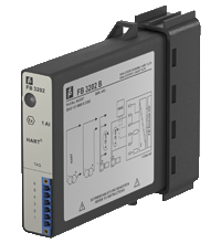
- 1-channel
- Fully compatible replacement for FB3203B
- Input Ex ia
- Installation in suitable enclosures in Zone 1
- Module can be exchanged under voltage (hot swap)
- Power supply for 2- or 3-wire transmitters with 4 mA ... 20 mA
- Supply circuit 15 V (20 mA)
- Input from active signals of 4-wire transmitters
- HART communication via field bus or service bus
- HART communication also for separately powered devices
- Simulation mode for service operations (forcing)
- Line fault detection (LFD) and Live Zero monitoring
- Permanently self-monitoring

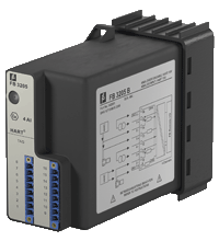
- 4-channel
- Inputs Ex ia
- Installation in suitable enclosures in Zone 1
- Module can be exchanged under voltage (hot swap)
- Power supply for 2-wire transmitters with 4 mA ... 20 mA
- Supply circuit 15 V (20 mA)
- Input from active signals of 4-wire transmitters
- Simulation mode for service operations (forcing)
- Line fault detection (LFD): one LED per channel
- Permanently self-monitoring
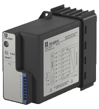
- 4-channel
- Inputs Ex ia
- Installation in suitable enclosures in Zone 1
- Module can be exchanged under voltage (hot swap)
- Power supply for 2-wire transmitters with 4 mA ... 20 mA
- Supply circuit 15 V (20 mA)
- Input from active signals of 4-wire transmitters
- HART communication via field bus or service bus
- Simulation mode for service operations (forcing)
- Line fault detection (LFD)
- Permanently self-monitoring

- 4-channel
- Outputs Ex ia
- Module can be exchanged under voltage (hot swap)
- Installation in suitable enclosures in Zone 1
- Analog output module for 0/4 mA ... 20 mA
- HART communication via field bus or service bus
- Simulation mode for service operations (forcing)
- Line fault detection (LFD): one LED per channel
- Permanently self-monitoring
- 4-channel
- Outputs Ex ia
- Installation in suitable enclosures in Zone 1
- Module can be exchanged under voltage (hot swap)
- Analog output module for 0/4 mA ... 20 mA
- HART communication via field bus or service bus
- Simulation mode for service operations (forcing)
- Line fault detection (LFD): one LED per channel
- Permanently self-monitoring
- Output with bus-independent safety shutdown
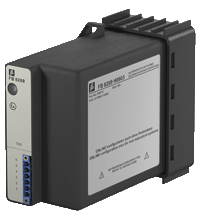
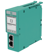
- Interface between the I/O modules and the PCS/PLC
- Com unit for 80 analog or 184 digital channels
- Communication via PROFIBUS DP

- Interface between the I/O modules and the PCS/PLC
- Com unit for 80 analog or 184 digital channels
- Communication via MODBUS TCP
- Installation in suitable enclosures in Zone 1
- Module can be exchanged under voltage (hot swap)
- HART communication via MODBUS TCP
- Configuration via FDT 1.2 DTM
- Non-volatile memory for configuration and parameter settings
- Self configuration in redundant systems
- Permanently self-monitoring
- Outputs drive to safe state in case of failures
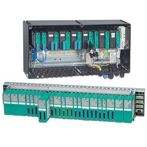
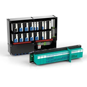
- Standard enclosure for FB-System
- Max. 5 slots for I/O modules
- For FOUNDATION Fieldbus H1
- Impact resistance enclosure, IP66/NEMA 4X
- Packaged certified solution
- Installation in Zone 1
- 4-channel
- Power supply for 2-wire transmitters with 4 mA ... 20 mA
- Installation in Zone 2 or safe area
- Supply circuit 15 V (20 mA)
- Input from active signals of 4-wire transmitters
- HART communication via field bus or service bus
- Simulation mode for service operations (forcing)
- Line fault detection (LFD): one LED per channel
- Permanently self-monitoring
- Module can be exchanged under voltage
- 4-channel
- Power supply for 2-wire transmitters with 4 mA ... 20 mA
- Installation in Zone 2 or safe area
- Supply circuit 21.5 V (4 mA)
- HART communication via field bus or service bus
- Simulation mode for service operations (forcing)
- Line fault detection (LFD): one LED per channel
- Permanently self-monitoring
- Module can be exchanged under voltage
- 4-channel
- Inputs Ex ia
- Mounting in Zone 2, Class I/Div.2 or in the safe area
- Power supply for 2-wire transmitters with 4 mA ... 20 mA
- Supply circuit 15 V (20 mA)
- Input from active signals of 4-wire transmitters
- HART communication via field bus or service bus
- Simulation mode for service operations (forcing)
- Line fault detection (LFD): one LED per channel
- Permanently self-monitoring
- Module can be exchanged under voltage
- 4-channel
- Inputs Ex ia
- Mounting in Zone 2, Class I/Div.2 or in the safe area
- Power supply for 2-wire transmitters with 4 mA ... 20 mA
- Supply circuit 15 V (20 mA)
- HART communication via field bus or service bus
- Simulation mode for service operations (forcing)
- Line fault detection (LFD): one LED per channel
- Permanently self-monitoring
- Module can be exchanged under voltage
- 8-channel
- Outputs Ex ib
- Mounting in Zone 2, Class I/Div.2 or in the safe area
- Module can be exchanged under voltage
- Galvanic group isolation
- Line fault detection (LFD)
- Positive or negative logic selectable
- Simulation mode for service operations (forcing)
- Permanently self-monitoring
- Output with watchdog
- Output with bus-independent safety shutdown
- Interface between the I/O modules and the PCS/PLC
- Com unit for 80 analog or 184 digital channels
- Communication via MODBUS RTU
- Mounting in Zone 2, Class I/Div.2 or in the safe area
- HART communication via service bus
- Configuration via FDT 1.2 DTM
- Non-volatile memory for configuration and parameter settings
- Self configuration in redundant systems
- Permanently self-monitoring
- Outputs drive to safe state in case of failures
- Module can be exchanged under voltage
- Interface between the I/O modules and the PCS/PLC
- Com unit for 80 analog or 184 digital channels
- Communication via PROFIBUS DP
- Mounting in Zone 2, Class I/Div.2 or in the safe area
- HART communication via PROFIBUS DP V1 or service bus
- Configuration via FDT 1.2 DTM
- Configuration in run (CiR) for any PCS
- Non-volatile memory for configuration and parameter settings
- Self configuration in redundant systems
- Permanently self-monitoring
- Outputs drive to safe state in case of failures
- Module can be exchanged under voltage
- Interface between the I/O modules and the PCS/PLC
- Com unit for 80 analog or 184 digital channels
- Communication via MODBUS TCP
- Mounting in Zone 2, Class I/Div.2 or in the safe area
- HART communication via MODBUS TCP or service bus
- Configuration via FDT 1.2 DTM
- Non-volatile memory for configuration and parameter settings
- Self configuration in redundant systems
- Permanently self-monitoring
- Outputs drive to safe state in case of failures
- Module can be exchanged under voltage
- Interface between the I/O modules and the PCS/PLC
- Mounting in Zone 2, Class I/Div.2 or in the safe area
- Non-volatile memory for configuration and parameter settings
- Communication via PROFINET
- HART communication via PROFINET and HART I/P
- Surge protection barrier for 2 signal lines
- Nominal voltage 24 V DC
- Surge protection barrier for grounded signal lines
- Max. surge current (8/20 ?µs) 20 kA
- Connection via screw terminals
- DIN rail mountable
- Up to SIL 3 acc. to IEC/EN 61508

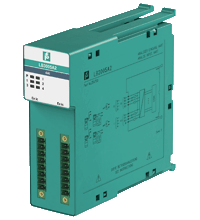
- 1-channel
- Input Ex ia
- Power supply for 2- or 3-wire transmitters with 4 mA ... 20 mA
- Module can be exchanged under voltage (hot swap)
- Installation in suitable enclosures in Zone 1
- Supply circuit 15 V (20 mA)
- Input from active signals of 4-wire transmitters
- HART communication via field bus or service bus
- HART communication also for separately powered devices
- Simulation mode for service operations (forcing)
- Line fault detection (LFD) and Live Zero monitoring
- Permanently self-monitoring

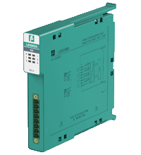
- 4-channel
- Inputs Ex ia
- Installation in suitable enclosures in Zone 1
- Module can be exchanged under voltage (hot swap)
- Power supply for 2-wire transmitters with 4 mA ... 20 mA
- Supply circuit 15 V (20 mA)
- Input from active signals of 4-wire transmitters
- HART communication via field bus or service bus
- Simulation mode for service operations (forcing)
- Line fault detection (LFD)
- Permanently self-monitoring
- 4-channel
- Inputs Ex ia
- Installation in suitable enclosures in Zone 1
- Module can be exchanged under voltage (hot swap)
- Converter for 2-, 3- and 4-wire RTDs (Pt100 ... Pt1000), slide wire sensors etc.
- Simulation mode for service operations (forcing)
- Line fault detection (LFD)
- Permanently self-monitoring
- 4-channel
- Outputs Ex ia
- Installation in suitable enclosures in Zone 1
- Module can be exchanged under voltage (hot swap)
- Line fault detection (LFD)
- Positive or negative logic selectable
- Simulation mode for service operations (forcing)
- Permanently self-monitoring
- Output with watchdog
- 4-channel
- Inputs Ex ia, Outputs Ex ia
- Installation in suitable enclosures in Zone 1
- Module can be exchanged under voltage (hot swap)
- Analog input, digital input,
analog output, digital output - Supply circuit 21.5 V (4 mA)
- HART communication via field bus or service bus
- Simulation mode for service operations (forcing)
- Line fault detection (LFD): one LED per channel
- Permanently self-monitoring

- Interface between the I/O modules and the PCS/PLC
- Com unit for 80 analog or 184 digital channels
- Communication via PROFIBUS DP
- Installation in suitable enclosures in Zone 1
- Module can be exchanged under voltage (hot swap)
- HART communication via PROFIBUS DP V1 or service bus
- Configuration via GSD parameters from the control system
- Non-volatile memory for configuration and parameter settings
- Self configuration in redundant systems
- Permanently self-monitoring
- Outputs drive to safe state in case of failures
Exploring Pepperl+Fuchs Remote IO Systems for Industrial Automation
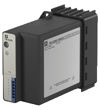
Pepperl+Fuchs provides two remote io systems for use in Zone 1 or Zone 2, FB and LB. Pepperl+Fuchs remote I/O systems bridge the gap between the existing technology base and the new control system. They are designed to solve engineering measurement and control problems in all hazardous areas or departments. These systems establish digital communication over various protocols for standard sensors and actuators, such as 4-20 mA devices, temperature and NAMUR sensors, and solenoid valves.
Remote modules can be easily connected to the backplane even during ongoing operation. They provide cost-effective energy management and low power dissipation. Modules with intrinsically safe and non-intrinsically safe outputs can be operated in parallel. You can use single-channel modules for single-loop integrity, multi-channel modules for high-density packaging, or a combination. Below, we will take a closer look at Pepperl+Fuchs remote io systems.
Advantages of Pepperl+Fuchs Remote IO Technology
Pepperl+Fuchs is renowned for its expertise in industrial automation and process control solutions, including remote I/O technology. Its advantages include.
Flexibility and scalability
Remote I/O systems provide flexibility in placing I/O modules, allowing for distributed installation over a large area. This makes scaling and adapting the system to changing process requirements easier.
Reduced wiring costs
By locating I/O modules closer to field devices, remote I/O technology minimizes the need for long-wiring connections to a central controller. This can result in significant savings in cabling and installation costs.
Increased reliability
Distributed I/O systems can improve the reliability of the entire control system. If one module or field device fails, it does not necessarily affect the whole system, unlike a centralized system where a failure can have broader consequences.
Ease of maintenance
With remote I/O, modules can be replaced or added without disrupting the entire system — this ease of maintenance results in reduced downtime and efficient troubleshooting.
Adaptability to harsh conditions
Pepperl+Fuchs is known for providing solutions for challenging industrial environments. Remote I/O technology can be designed to withstand harsh environments such as extreme temperatures, humidity, and vibration.
Integration with Fieldbus networks
Remote IO Network is compatible with various industrial communications protocols and Fieldbus networks, allowing for seamless integration with other devices and systems in the enterprise.
Advanced Diagnostics
Remote I/O systems often include diagnostic functions that provide real-time information about the status of field devices. This can make preventive maintenance and troubleshooting easier.
Cost-effective expansion
When the need arises to expand the I/O capabilities of a control system, remote I/O technology allows for cost-effective expansion by adding additional modules where needed.
Installation and Configuration Tips
Installing and configuring Pepperl+Fuchs Remote IO involves several steps to ensure a successful implementation. Here are some tips that you may find helpful.
Checking the documentation
Start by carefully reading the product manuals, technical specifications, and installation guides provided by Pepperl+Fuchs. This documentation contains essential information about the hardware, wiring, and setup steps.
System planning
Plan the layout of your remote I/O system based on factors such as the distance between I/O modules, the location of field devices, and environmental conditions. Ensure that the selected locations meet the specified installation requirements.
Power supply stabilization
Ensure stable and sufficient power supply for remote I/O modules. Follow the manufacturer's recommendations for power requirements and provide redundancy for mission-critical applications.
Correct wiring
Follow the recommended connection methods outlined in the documentation. Use the correct cable types, connectors, and connection methods to ensure reliable communications and prevent signal interference.
Addressing and setup
Assign unique addresses to each remote I/O module to avoid conflicts. This is essential for proper communication between the modules and the central controller. Customize the system to meet the requirements of your management strategy.
Fieldbus network configuration
Configure the network parameters according to your application if your remote I/O system interfaces with a Fieldbus network (e.g., PROFIBUS, PROFINET). Ensure compatibility between the remote I/O modules and the selected fieldbus protocol.
Testing and commissioning
Conduct thorough testing and commissioning before putting the system into the entire operation. Check each I/O module, field device, and communication link for proper function. Resolve any problems or inconsistencies that arise during this testing phase.
Documenting and labeling
Maintain detailed documentation of installation, configuration, and addressing scheme. Label all cables, modules, and field devices for easy identification during maintenance and troubleshooting.
Training and onboarding
Train the personnel responsible for operating and maintaining the remote I/O system. Ensure they are familiar with the system architecture, configuration tools, and diagnostic features.
Regular maintenance
Create a routine maintenance schedule to check the system, check for loose connections, and promptly resolve any problems. Regular maintenance contributes to the long-term reliability of remote I/O technology.
Selecting the Right Remote IO System for Your Industry
Selecting the suitable Pepperl+Fuchs systems remote i/o for your industry involves considering several key factors to ensure that the chosen solution meets your specific requirements and objectives. Here are some aspects to consider.
General requirements
Clearly define the requirements of your industrial application. Consider factors such as the required number and types of I/O points, required communication protocols, environmental conditions, and any specific features necessary for your process.
Environmental conditions
Assess the environmental conditions in which the remote I/O system will operate. Consider factors such as extreme temperatures, humidity, exposure to chemicals, and potential exposure to dust or water. Pepperl+Fuchs offers solutions designed for various industrial environments, including hazardous areas.
Communication protocols
Determine the communication protocols that your existing control system or Fieldbus network supports. Make sure that the selected remote I/O system is compatible with these protocols. Pepperl+Fuchs supports industrial communication standards such as PROFIBUS, PROFINET, and others.
Integration with the control system
Ensure compatibility and seamless integration with your existing management system. The remote I/O system must support your controller's communication requirements and allow easy integration into your automation architecture.
Modularity and scalability
Consider the modularity and scalability of the remote I/O system. The modular system allows you to quickly expand or modify the system as your application requirements change. Pepperl+Fuchs typically offers modular solutions that can be adapted to projects of different sizes.
Power supply requirements
Review the power supply requirements for the remote I/O system. Ensure that the system can receive sufficient power based on the available power sources in your facility. Consider redundancy options for mission-critical applications.
Safety and certification
If your industry involves hazardous areas or requires special safety certifications, make sure your remote I/O system meets the required standards. Pepperl+Fuchs is renowned for its expertise in developing solutions for dangerous areas.
Diagnostic and monitoring functions
Experience the diagnostic and monitoring features offered by the remote I/O system. Advanced diagnostic capabilities can simplify troubleshooting and maintenance, reducing downtime in your operation.
Ease of set up and maintain
Consider ease of setup and maintenance. Look for systems that provide user-friendly tools and configuration interfaces. Remote I/O systems that are easy to set up and maintain can help improve operational efficiency.