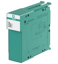
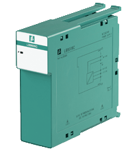
Pepperl+Fuchs Remote IO Systems
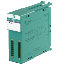
- 8-channel
- Contact 30 V AC/DC, 1 A, 30 W, 30 VA (resistive load)
- Mounting in Zone 2, Class I/Div.2 or in the safe area
- Positive or negative logic selectable
- Simulation mode for service operations (forcing)
- Permanently self-monitoring
- Output with watchdog
- Module can be exchanged under voltage
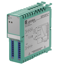
- 8-channel
- Galvanic group isolation
- Installation in Zone 2 or safe area
- Module can be exchanged under voltage
- Line fault detection (LFD)
- Positive or negative logic selectable
- Simulation mode for service operations (forcing)
- Permanently self-monitoring
- Output with watchdog
- Output with bus-independent safety shutdown
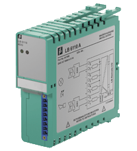
- 4-channel
- Outputs Ex ia
- Installation in Zone 2 or safe area
- Line fault detection (LFD)
- Positive or negative logic selectable
- Simulation mode for service operations (forcing)
- Permanently self-monitoring
- Output with watchdog

- 4-channel
- Outputs Ex ia
- Installation in Zone 2 or safe area
- Line fault detection (LFD)
- Positive or negative logic selectable
- Simulation mode for service operations (forcing)
- Permanently self-monitoring
- Output with watchdog
- Output with bus-independent safety shutdown

- 4-channel
- Outputs Ex ia
- Installation in Zone 2 or safe area
- Line fault detection (LFD)
- Positive or negative logic selectable
- Simulation mode for service operations (forcing)
- Permanently self-monitoring
- Output with watchdog
- 2-channel
- Outputs Ex ia
- Mounting in Zone 2, Class I/Div.2 or in the safe area
- Line fault detection switched on and off
- Positive or negative logic selectable
- Simulation mode for service operations (forcing)
- Permanently self-monitoring
- Output with watchdog
- Output with bus-independent safety shutdown
- Module can be exchanged under voltage (hot swap)
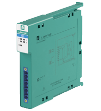
- 4-channel
- Analog input, digital input,
analog output, digital output - Installation in Zone 2 or safe area
- Supply circuit 21.5 V (4 mA)
- HART communication via field bus or service bus
- Simulation mode for service operations (forcing)
- Line fault detection (LFD): one LED per channel
- Permanently self-monitoring
- Module can be exchanged under voltage
- 4-channel
- Inputs Ex ia, Outputs Ex ia
- Analog input, digital input,
analog output, digital output - Mounting in Zone 2, Class I/Div.2 or in the safe area
- Supply circuit 15 V (20 mA)
- HART communication via field bus or service bus
- Simulation mode for service operations (forcing)
- Line fault detection (LFD): one LED per channel
- Permanently self-monitoring
- Module can be exchanged under voltage

- Interface between the I/O modules and the PCS/PLC
- Com unit for 80 analog or 184 digital channels
- Communication via PROFIBUS DP
- Mounting in Zone 2, Class I/Div.2 or in the safe area
- HART communication via PROFIBUS DP V1 or service bus
- Configuration via GSD parameters from the control system
- Non-volatile memory for configuration and parameter settings
- Self configuration in redundant systems
- Permanently self-monitoring
- Outputs drive to safe state in case of failures
- Module can be exchanged under voltage
- Interface between the I/O modules and the PCS/PLC
- Com unit for 80 analog or 184 digital channels
- Communication via MODBUS RTU
- Mounting in Zone 2, Class I/Div.2 or in the safe area
- HART communication via service bus
- Configuration via FDT 1.2 DTM
- Non-volatile memory for configuration and parameter settings
- Self configuration in redundant systems
- Permanently self-monitoring
- Outputs drive to safe state in case of failures
- Module can be exchanged under voltage

- Interface between the I/O modules and the PCS/PLC
- Com unit for 80 analog or 184 digital channels
- Communication via PROFIBUS DP
- Mounting in Zone 2, Class I/Div.2 or in the safe area
- HART communication via PROFIBUS DP V1 or service bus
- Configuration via FDT 1.2 DTM
- Configuration in run (CiR) for any PCS
- Non-volatile memory for configuration and parameter settings
- Self configuration in redundant systems
- Permanently self-monitoring
- Outputs drive to safe state in case of failures
- Module can be exchanged under voltage
- Power supply for 24 V
- Permits vertical or horizontal mounting in Zone 2
- Use three power supplies for redundancy
- Galvanic isolation to mains
- Supply of I/O modules and com units
- Mounting in Zone 2, Class I/Div.2 or in the safe area
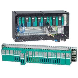
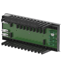
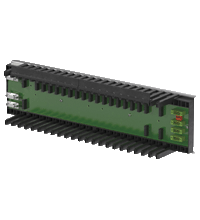
- Backplane for LB-System
- For MODBUS TCP/IP
- Max. 22 slots for I/O modules
- Redundancy (field bus and power supply)
- Mounting in Zone 2, Class I/Div.2 or in the safe area
- Backplane for LB-System
- For PROFIBUS DP, PROFIBUS DP V1, PROFINET, and MODBUS RTU
- Max. 22 slots for I/O modules
- 5 SIL 2 output shutdown segments
- Redundancy (field bus and power supply)
- Mounting in Zone 2, Class I/Div.2 or in the safe area
- Backplane for LB-System
- For MODBUS TCP/IP
- Max. 8 slots for I/O modules
- Mounting in Zone 2, Class I/Div.2 or in the safe area
- Backplane for LB-System
- For PROFIBUS DP, PROFIBUS DP V1, PROFINET, and MODBUS RTU
- Max. 8 slots for I/O modules
- Mounting in Zone 2, Class I/Div.2 or in the safe area
- Backplane for LB-System
- Fieldbus type determined by base backplane
- Max. 24 slots for I/O modules
- 5 SIL 2 output shutdown segments
- Redundancy (power supply)
- Mounting in Zone 2, Class I/Div.2 or in the safe area
- Backplane for LB-System
- For MODBUS TCP/IP
- Max. 16 slots for I/O modules
- Mounting in Zone 2, Class I/Div.2 or in the safe area
- Backplane for LB-System
- For PROFIBUS DP, PROFIBUS DP V1, PROFINET, and MODBUS RTU
- Max. 16 slots for I/O modules
- Mounting in Zone 2, Class I/Div.2 or in the safe area
- Max. 5 slots for I/O modules (dual width only)
- For FOUNDATION Fieldbus H1
- Backplane for LB-System
- Mounting in Zone 2, Class I/Div.2 or in the safe area
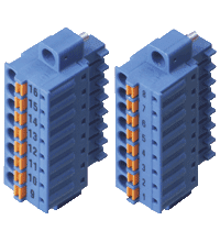
- Spring terminal
- For LB and FB modules
- 2 x 8-pole
- Labeled 1 ... 8 and 9 ... 16
- Color blue
- For Ex ia or Ex ib applications
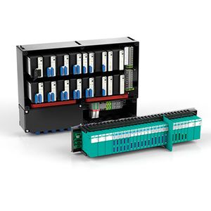
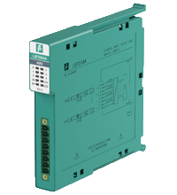
Remote I/O Unit
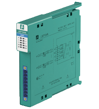
Remote I/O Unit
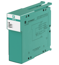
Remote I/O Unit