General Troubleshooting Of VFD Problems
22.12.2023
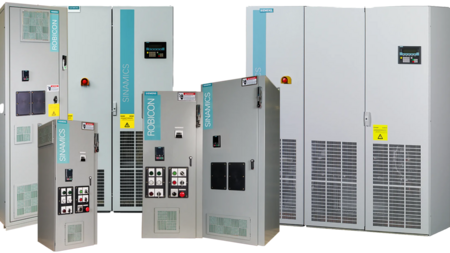
Equipment, the main part of which is rotating mechanisms with power supply, is used in various industrial spheres. Most of these units are involved in some kind of production cycle. They are characterized by the presence of an electric motor, which changes the speed of rotation (e.g. a fan or a Grundfos VFD pump controller) during operation. Different modes of operation of such devices require different types of electric current supply. Frequency converters should be connected for normal, uninterrupted operation of the equipment in different modes.

The ability to change the voltage frequency makes it possible to change the power delivered to the load not discretely, but continuously. Due to this principle of operation, a variable frequency drive can smoothly regulate the rotation parameters of the Grundfos troubleshooting.
- Advantages of using variable frequency drives for control.
- Makes it easier to start the drive.
- Allows the motor to run for a long time, regardless of the degree of loading.
- Provides greater accuracy of adjusting operations.
- Allows condition monitoring of individual components in industrial electrical circuits. This makes it possible to keep a permanent record of the amount of time worked by motors to evaluate their performance later.
- The presence of electronic components makes it possible to diagnose faults in motor operation remotely.
- Various feedback sensors (pressure, temperature) can be connected to the device. As a result, the rotation speed will be stable under constantly changing loads.
- In case of loss of mains voltage, controlled braking and restart will be activated.
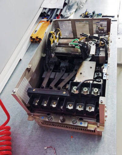
Frequency inverters do not require daily maintenance, but regular maintenance extends the service life. The period of maintenance depends on operating conditions. The condition of the heatsink should be monitored visually and the performance of the built-in fan on the frequency converter heatsink should be checked. If the radiator is contaminated, due to poor cooling, overheating and subsequent failure of the drive is possible. When contaminated with media such as oil, soot, metal chips - requires complete disassembly and inspection of all components of the converter.
Only qualified personnel can service and troubleshoot frequency converters. Turn off the frequency converter before proceeding with VFD troubleshooting procedures if real-time troubleshooting is not required.
Pay attention to the internal components of the frequency converter that are under high voltage. The DC bus voltage does not disappear immediately after you disconnect it from the mains. As a rule, frequency converters (FC) are equipped with a voltage indicator, but in any case, before disassembling the FC, it is necessary to make sure that there is no residual charge on the DC bus.
Adjustment of the control system of the frequency converter is carried out by feeding it with supply voltage without power voltage. An oscilloscope allows you to check whether the duration of pulses supplied to the inverter corresponds to that specified in the datasheet. If the signals are distorted, the corresponding elements of the system are removed and replaced. Integrated circuits are used for the operation of modern frequency converters. When repairing and adjusting systems, in addition to oscilloscopes and testers, special equipment is used.
After the overhaul, the unit should be run at idle speed. Then, if everything is normal, run the inverter with the motor at idle, but without its load. In working on such a mode, it is important to check the absence of overheating of the drive elements. The final check of the drive operation is carried out at the nominal value of the motor load.
After troubleshooting VFD drives of the equipment, it is sometimes necessary to come to a certain voltage/frequency ratio. The frequency rating should be the same as the voltage rating. To properly set up the EFD you must perform operations such as:
- Measurement of the voltage transformer transformation ratio and the stator active resistance of the electric motor;
- Calculation of the voltage drop equal to the product of the stator resistance values by the motor rated current divided by the transformation ratio.
- As a result, the voltage taken from the resistor tap connected parallel to the transformer secondary must be equal to the calculated value.
Failure in the power circuit may be caused by sudden oscillations in the inverter-motor system. This can be eliminated by adjusting the control unit resistor.
How to test VFDs with a multimeter
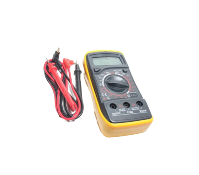
Perhaps there is no more useful and practical electronic device than a multimeter. Accordingly, there are a huge number of different models on the market for all tastes and wallets. Naturally, the cheaper the device, the fewer functions it performs and the lower its accuracy. To improve the accuracy and reliability of the measurements, multimeter manufacturers add various functions and improvements to the design and circuitry.
Some time ago, multimeters started adding the TRUE RMS function, which allows the readings to be corrected for voltage non-sinusoidal. Up to a certain period, this was quite acceptable, however, the appearance in large numbers in electrical households of various devices that work on the principle of frequency synthesis made this function insufficient to achieve accuracy.

The fact is that the frequency synthesis is associated with the presence of parasitic HF harmonics in voltage and current, which affect the accuracy of measurements, especially for AC and voltage. Moreover, the presence of harmonics significantly affects the state of the power grid as a whole, but this is a topic for separate consideration. As an example, let's try to make test measurements of voltage on the motor, which is fed through a frequency converter built on transistors. It is known that such converters synthesize mainly a trapezoidal voltage form, which contains many harmonics of high orders.
However, electricians need to know - what is the value of the effective voltage of the main harmonic, close to 50 Hz, because it is this harmonic that makes the motor work. A multimeter without this function turned on shows that our voltage is 216 Volts and frequency is 3.7 kHz although the frequency converter shows that the real frequency is 50.3 Hz and the motor runs fine.
VFD failure causes
Modern frequency inverters have their internal memory. It is designed to record all monitored parameters during the operation of the inverter. With a sufficient amount of data, the control system can compare and analyze its performance data.
Based on the collected data, the error code function allows you to generate a certain numerical value of the fault and record it in the error log of the internal memory. For easy monitoring and diagnosis of faults, the frequency converter faults are displayed on the device display. The value of the code determines the type of fault and the ways of its elimination.
Adjustment of the converter is carried out with the use of high-frequency oscilloscopes.
The operation of the frequency converter is checked in three possible modes, these are:
- in nominal mode;
- at idle running;
- at the maximum permissible overload.
Inactivation of thyristors (transistors) of a frequency converter or break in a power circuit is determined by the shape of the output voltage of the converter. After that, in the thyristor unit is installed a thyristor chosen due to the required parameters, to replace the damaged thyristor.
Probable abb VFD troubleshooting:
- Dust accumulation. Significant dust accumulation occurs mainly in heavy industry and food industry (cement works, stone working, grain mills). This occurs due to inadequate sealing of the housing or damage to the housing. Settled dust disturbs the cooling process. The result is overheating and shortening the service life of the frequency converter. Conductive dust can cause insulation breakdown. Short-circuiting of the control board can provoke frequency converter errors.
- Oil contamination and erosion. Machine and transformer oil can cause serious damage to the inverter. The oil that gets on the electronic parts and control boards of the inverter, over time, destroys individual elements, which can lead to fire and the explosion of the unit. The surest way to extend the operating life of the unit is to install a special protective enclosure. This will prevent flammable or combustible liquids or gases from entering the unit. 3.
- Faults in the multi-function input/output terminals. This type of failure is caused by excessive wear on the unit's connectors and terminals. Non-compliant operating conditions can also cause this problem. If the connectors' operating life is significantly exceeded, the I/O circuits on the power board may simply burn out.
VFD troubleshooting manual: improper installation. The following omissions are often encountered during the installation and wiring of the inverter:
- the thickness of the cross-section of the mounting wire or cable strands is less than the allowable values;
- incorrect connection of electric wiring;
- the presence of bad electric contact in the place of connection of terminals and wires;
- violation of insulation of cable strands or mounting wires (there is a possibility of bare wires touching the device case).
VFD overcurrent fault
Overload is one of the most common faults, which causes disconnection of the inverter. ABB overcurrent fault include motor overload, which can be caused by too short acceleration time, too much DC braking, too low mains voltage, too much load, etc. These can usually be eliminated by delaying the acceleration time and checking the mains voltage.
 First, it should be analyzed whether it is an overload of the motor or an overload of the frequency converter itself. Generally speaking, since the motor overload capacity is relatively high, motor overloading is unlikely to occur if the frequency converter motor parameters are set correctly.
The main causes of overloading:
- The main characteristic of too much mechanical load: motor heating, this can be checked by reading the operating current on the screen.
- Skewed three-phase voltage will cause an overcurrent of a particular phase and result in an overload trip. This shows unbalanced motor heating, and you won't be able to find it by reading the operating current on the display screen (since the display only shows one phase current).
- Inside the frequency converter, there is a fault in the current test unit and the measured current signal is too high, causing the frequency converter to trip.
If the motor temperature does not rise, check if the electronic thermal protection function of the frequency converter is set correctly. If the resulting overloads are normal, this is an indication that the inverter is not properly selected. It is necessary to increase the capacity of the frequency converter or replace it with another frequency converter. This is because when the motor is overloaded, short-term overloading is allowed as long as the increasing temperature does not exceed the rated value.
The frequency converter does not allow this. If the motor temperature increases too much and the resulting overloads are normal, this indicates that the motor overload is too great. By this point, the first thing to consider is the proper addition of a gear ratio to reduce motor shaft overloading. If the gear ratio can be added, then add it. If it cannot be added, then the motor power should be added.
If the Inverter output voltage is balanced, the problem is in the wiring between the inverter and the motor. Therefore, check that all screws on the connection terminals are tight. If there are contractors or other electrical equipment between the frequency converter and the motor, check that all connectors of the relevant electrical equipment are tightened and that all contractors are in good condition.
If no cause is found by checking the steps above, check for any malfunctions. The method of evaluation is to measure the output current of the Inverter using an ammeter under light load or no-load conditions. Compare the output current with the operating current displayed on the screen, if the current value on the screen is much higher than the measured current, it means that there are many errors in the current measurement inside the frequency converter and the "overload" tripping may be caused by faults.
Periodic inspection and maintenance can help prevent several problems, but frequency inverters do fail, and this cannot be completely avoided. In case of a serious breakdown, it is necessary to diagnose the equipment. The most responsible activity is the search for damaged parts. After all, it happens that you have to look for a floating fault when it occurs periodically under certain conditions or just chaotically. In the workshop, you will have qualified diagnostics, which includes mainly: reading error codes, determining the failed nodes. Be prepared to pay for the repair.