How does a pneumatic valve work? Overview of different types of pneumatic valves and their working principle.
08.12.2019
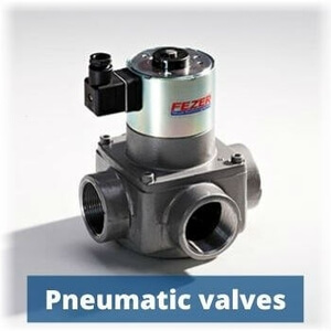
Pneumatic valve is a valve that operates inside a pneumatic system (a system that operates with pressurized air or gas).
CONTENTS:
- What is pneumatic valve?
- Pneumatic valve types and design
- Pneumatic flow control valve working principle
What is pneumatic valve?
Pneumatics is a system that uses a difference in pressure of compressed gas or air for its operation. Such schemes contain a number of different mechanisms through which compressed gas is distributed. All together, they act as a centralized system.
Valves are used to control, distribute and direct the flow in this structure. They perform a guiding and dosing function via locking and regulating elements. Thus, pneumatic valves act as a mediator between the source (compressor) and actuators (such as pneumatic actuator, pneumatic cylinder) in pneumatics.
Such units are driven by special signals. The following types of signals can control pneumatic valves:
- electromagnetic
- pneumatic
- mechanical
Electromagnetic pneumatic valves are controlled by magnetic fields on coils and solenoid. Their working principle is quite simple. Current from an external electrical source is supplied to the coils. Interaction between the magnetic field in the coils and in solenoid makes the valve stem move.
Pneumatically operated valves are typically controlled by the same stream of compressed air that operates in the pneumatic system. Its presence or absence affects their work in certain conditions.
Mechanical pneumatic valves are driven by mechanical force, for example, using a lever. There are many options, for example in 90-degree steps or a quarter turn versions. Most often, they perform simple tasks (opening/closing).
In addition to the main categories, devices with a combined control are also manufactured. In some valves, control perform manually, for example, just using a button.
Pneumatic valve types and design
The main characteristics that determine the type of valve are a number of flow lines (ports) and possible mechanism positions. These numbers are always primarily indicated in the valve characteristics.
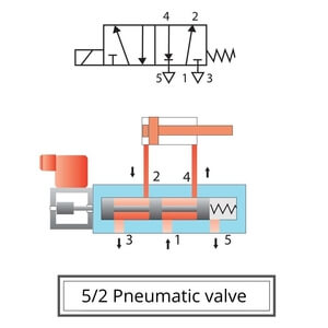
The first figure always indicates the number of ports in the device and the second one shows available spool positions. For example, a 4/2 pneumatic valve means that it has four ports and two possible spool positions.
The use of the sign between the numbers is not regulated and it may be chosen by a producer (4/3, 4-3, etc.). The most common models in pneumatic systems are valves with a 3/2 and 5/2 scheme.
A figure of lines means the number of connecting holes. Each of the holes and its bundles is designed for specific functions. Their main purpose is to retract and extend the medium and exhaust.
The figure of positions indicates how many possible options for switching the position of the valve are available for adjustment.
There are two types of valves according to the initial position of the spool relative to the flow:
- Normally open
- Normally closed
A normally-closed valve means that in the initial state its section is closed (air-flow is blocked). When a signal is given, the valve opens, thereby opening the section of the line.
A normally-open valve initially has an open flow line (airflow moves freely) and closes it when a signal is given.
In addition, devices may differ in the way they return to their original position after completing the work. There are two types:
- Monostable
- Bistable
Mono-stable valves return to their original position after the termination of the signal. This is achieved using a return spring. They need one external signal to work.
Bi-stable valves remain in the position in which the external signal ceased and do not return to their original position. To back them to their initial position, a special return signal is needed. Therefore, such category requires two external signals to operate (on/off).
Pneumatic flow control valve working principle
The main task of the pneumatic distributor is to change the cross-section in the pneumatic pipeline, which allows adjusting and directing the flow.
As mentioned above, this action is performed by the locking and regulating elements.
There are two types of section changes: discrete (on / off) or smoothly continuous (with adjustable parameters).
This purpose divides the equipment into two main structural types:
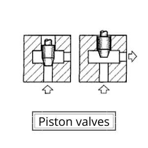
- Piston
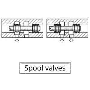
- Spool
Piston valves are designed for discrete flow control. This type of control provides quick isolation between the channels. It is the most suitable for small systems with simple tasks. The valve seat moves along the flow line. Such design usually has only 2-3 outputs.
Sliding spool valves are designed to make more complex flow control operations. That equipment can be used in cross-sections with a high flow rate and a complicated circuit. Spool valves can work in systems with 4-5 working lines, as well as in simpler circuits, due to their versatility. The spool moves perpendicular to the flow axis.
Conclusion: pneumatic valves are the main regulators of compressed air and gas flow in pneumatic systems. Due to their wide variety, they can perform different complicated and simple tasks in the flow direction control. Each of the valves has its own special design.
Eltra Trade offers a wide selection of pneumatic valves from leading companies such as Burkert, SMC, Norgren, Univer, and more. Our expert managers are always ready to assist with selection and answer any questions.