Pepperl+Fuchs Explosion Protection
Choose a subcategory:
Show all categories
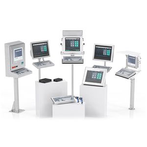
Visualization Equipment
Visualization Equipment
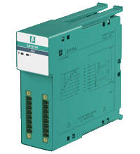
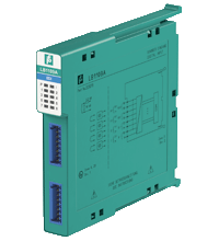
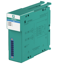
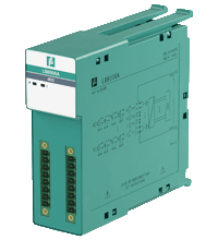
- 8-channel
- Inputs Ex ic
- Installation in Zone 2 or safe area
- Dry contact or NAMUR inputs
- Positive or negative logic selectable
- Simulation mode for service operations (forcing)
- Line fault detection (LFD)
- Permanently self-monitoring
- Module can be exchanged under voltage
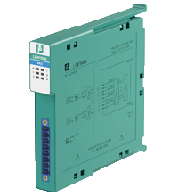
- 15-channel
- Active digital signal 24 V DC
- Installation in Zone 2 or safe area
- Positive or negative logic selectable
- Simulation mode for service operations (forcing)
- Permanently self-monitoring
- Module can be exchanged under voltage

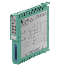
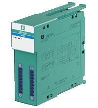
- 2 channels
- Inputs Ex ia
- Mounting in Zone 2, Class I/Div.2 or in the safe area
- Dry contact or NAMUR inputs
- Galvanic isolation between channels and the bus
- Positive or negative logic selectable
- Simulation mode for service operations (forcing)
- Line fault detection (LFD)
- Permanently self-monitoring
- Module can be exchanged under voltage
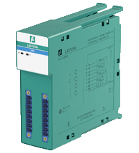
- 3-channel
- Inputs Ex ia
- Mounting in Zone 2, Class I/Div.2 or in the safe area
- Dry contact or NAMUR inputs
- Positive or negative logic selectable
- Simulation mode for service operations (forcing)
- Line fault detection (LFD)
- Permanently self-monitoring
- Module can be exchanged under voltage
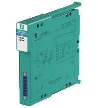
- 1-channel
- Input Ex ia
- Mounting in Zone 2, Class I/Div.2 or in the safe area
- Input for frequency, counter, direction of rotation
- Digital input max. 15 kHz
- Positive or negative logic selectable
- Simulation mode for service operations (forcing)
- Line fault detection (LFD)
- Permanently self-monitoring
- Module can be exchanged under voltage
- 8-channel
- Inputs Ex ia
- Mounting in Zone 2, Class I/Div.2 or in the safe area
- Dry contact or NAMUR inputs
- Positive or negative logic selectable
- Simulation mode for service operations (forcing)
- Line fault detection (LFD)
- Permanently self-monitoring
- Module can be exchanged under voltage
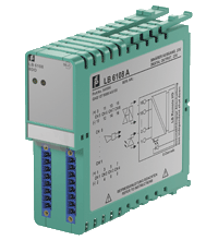
- 1 digital output, 2 digital inputs
- Inputs and output Ex ia
- Mounting in Zone 2, Class I/Div.2 or in the safe area
- Positive or negative logic selectable
- Simulation mode for service operations (forcing)
- Line fault detection (LFD)
- Permanently self-monitoring
- Output with watchdog
- Module can be exchanged under voltage
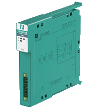
- 1-channel
- Input Ex ia
- Mounting in Zone 2, Class I/Div.2 or in the safe area
- Power supply for 2- or 3-wire transmitters with 4 mA ... 20 mA
- Supply circuit 15 V (20 mA)
- Input from active signals of 4-wire transmitters
- HART communication via field bus or service bus
- HART communication also for separately powered devices
- Simulation mode for service operations (forcing)
- Line fault detection (LFD) and Live Zero monitoring
- Permanently self-monitoring
- Module can be exchanged under voltage
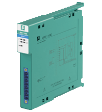
- 1-channel
- Analog output module for 0/4 mA ... 20 mA
- Installation in Zone 2 or safe area
- HART communication via field bus or service bus
- Simulation mode for service operations (forcing)
- Line fault detection (LFD)
- Permanently self-monitoring
- Module can be exchanged under voltage
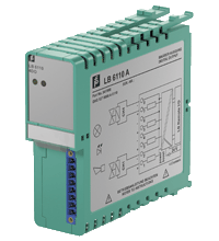
- 4-channel
- Outputs Ex ia
- Mounting in Zone 2, Class I/Div.2 or in the safe area
- Analog output module for 0/4 mA ... 20 mA
- HART communication via field bus or service bus
- Simulation mode for service operations (forcing)
- Line fault detection (LFD): one LED per channel
- Permanently self-monitoring
- Module can be exchanged under voltage
- 4 channels
- Inputs Ex ia
- Mounting in Zone 2, Class I/Div.2 or in the safe area
- Converter for 2-, 3- and 4-wire RTDs (Pt100 ... Pt1000), slide wire sensors etc.
- Simulation mode for service operations (forcing)
- Line fault detection (LFD)
- Permanently self-monitoring
- Module can be exchanged under voltage
- 4 channels
- Inputs Ex ia
- Mounting in Zone 2, Class I/Div.2 or in the safe area
- Converter for thermocouples and mV-signals
- Simulation mode for service operations (forcing)
- Line fault detection (LFD)
- Permanently self-monitoring
- Module can be exchanged under voltage
- 8-channel
- Contact 30 V AC/DC, 1 A, 30 W, 30 VA (resistive load)
- Mounting in Zone 2, Class I/Div.2 or in the safe area
- Positive or negative logic selectable
- Simulation mode for service operations (forcing)
- Permanently self-monitoring
- Output with watchdog
- Module can be exchanged under voltage
- 8-channel
- Galvanic group isolation
- Installation in Zone 2 or safe area
- Module can be exchanged under voltage
- Line fault detection (LFD)
- Positive or negative logic selectable
- Simulation mode for service operations (forcing)
- Permanently self-monitoring
- Output with watchdog
- Output with bus-independent safety shutdown
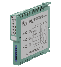
- 4-channel
- Outputs Ex ia
- Installation in Zone 2 or safe area
- Line fault detection (LFD)
- Positive or negative logic selectable
- Simulation mode for service operations (forcing)
- Permanently self-monitoring
- Output with watchdog

- 4-channel
- Outputs Ex ia
- Installation in Zone 2 or safe area
- Line fault detection (LFD)
- Positive or negative logic selectable
- Simulation mode for service operations (forcing)
- Permanently self-monitoring
- Output with watchdog
- Output with bus-independent safety shutdown

- 4-channel
- Outputs Ex ia
- Installation in Zone 2 or safe area
- Line fault detection (LFD)
- Positive or negative logic selectable
- Simulation mode for service operations (forcing)
- Permanently self-monitoring
- Output with watchdog
- 2-channel
- Outputs Ex ia
- Mounting in Zone 2, Class I/Div.2 or in the safe area
- Line fault detection switched on and off
- Positive or negative logic selectable
- Simulation mode for service operations (forcing)
- Permanently self-monitoring
- Output with watchdog
- Output with bus-independent safety shutdown
- Module can be exchanged under voltage (hot swap)
- 4-channel
- Analog input, digital input,
analog output, digital output - Installation in Zone 2 or safe area
- Supply circuit 21.5 V (4 mA)
- HART communication via field bus or service bus
- Simulation mode for service operations (forcing)
- Line fault detection (LFD): one LED per channel
- Permanently self-monitoring
- Module can be exchanged under voltage
- 4-channel
- Inputs Ex ia, Outputs Ex ia
- Analog input, digital input,
analog output, digital output - Mounting in Zone 2, Class I/Div.2 or in the safe area
- Supply circuit 15 V (20 mA)
- HART communication via field bus or service bus
- Simulation mode for service operations (forcing)
- Line fault detection (LFD): one LED per channel
- Permanently self-monitoring
- Module can be exchanged under voltage

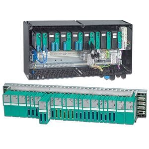
- Interface between the I/O modules and the PCS/PLC
- Com unit for 80 analog or 184 digital channels
- Communication via PROFIBUS DP
- Mounting in Zone 2, Class I/Div.2 or in the safe area
- HART communication via PROFIBUS DP V1 or service bus
- Configuration via GSD parameters from the control system
- Non-volatile memory for configuration and parameter settings
- Self configuration in redundant systems
- Permanently self-monitoring
- Outputs drive to safe state in case of failures
- Module can be exchanged under voltage
- Interface between the I/O modules and the PCS/PLC
- Com unit for 80 analog or 184 digital channels
- Communication via MODBUS RTU
- Mounting in Zone 2, Class I/Div.2 or in the safe area
- HART communication via service bus
- Configuration via FDT 1.2 DTM
- Non-volatile memory for configuration and parameter settings
- Self configuration in redundant systems
- Permanently self-monitoring
- Outputs drive to safe state in case of failures
- Module can be exchanged under voltage

- Interface between the I/O modules and the PCS/PLC
- Com unit for 80 analog or 184 digital channels
- Communication via PROFIBUS DP
- Mounting in Zone 2, Class I/Div.2 or in the safe area
- HART communication via PROFIBUS DP V1 or service bus
- Configuration via FDT 1.2 DTM
- Configuration in run (CiR) for any PCS
- Non-volatile memory for configuration and parameter settings
- Self configuration in redundant systems
- Permanently self-monitoring
- Outputs drive to safe state in case of failures
- Module can be exchanged under voltage