Pepperl+Fuchs Industrial Sensors
Choose a subcategory:
Show all categories
- Inputs for 2-, 3-, and 4-wire sensors
- Power supply of outputs from the external auxiliary voltage
- Supply of sensors from AS-Interface
- Function display for bus, external auxiliary voltage, in- and outputs
- Red LED per channel, lights up in the event of output overload
- Communication monitoring
- Switchable lead breakage detection (outputs)
- Cable piercing method with gold plated contact pins
- Degree of protection IP68 / IP69K
- AS-Interface POWER24
- Inputs for 2-, 3-, and 4-wire sensors
- Power supply of outputs from the external auxiliary voltage
- Supply of sensors from AS-Interface
- Function display for bus, external auxiliary voltage, in- and outputs
- Red LED per channel, lights up in the event of output overload
- Communication monitoring
- Switchable lead breakage detection (outputs)
- Degree of protection IP68 / IP69K
- AS-Interface POWER24
- One-piece housing with stainless steel base
- Installation without tools
- Metal threaded inserts with SPEEDCON technology
- Flat cable connection with cable piercing technique, variable flat cable guide
- Red LED per channel, lights up in the event of output overload
- Communication monitoring, configurable
- Inputs for 2-, 3-, and 4-wire sensors
- DIN rail mounting
- AS-Interface certificate
- Compact design
- Connections via round connector
- AS-Interface connection via M12 metal threaded insert with SPEEDCON
- Function display for bus, ext. auxiliary voltage, inputs and outputs
- Degree of protection IP67 / IP68 / IP69K
- Inputs for 2- and 3-wire sensors
- Supply for inputs from AS-Interface
- Power supply of outputs from the external auxiliary voltage
- Communication monitoring
- Detection of overload on sensor supply
- Detection of output overload with LED per channel
- Inputs for 3-wire sensors
- Outputs for DC roller motors (drum motors)
- Connection of motors and sensors via M8 connectors
- Configurable starting ramp
- Communication monitoring
- Supply for inputs from AS-Interface
- Power supply of outputs from the external auxiliary voltage
- Function display for bus, external auxiliary voltage, in- and outputs
- Cable piercing method with gold plated contact pins
- Degree of protection IP65
- Flat or round cable connection (via standardized EEMS base, not included with delivery)
- Cable piercing method for flat cable
- Communication monitoring, turn-off
- Inputs for 2- and 3-wire sensors
- Power supply of outputs from the external auxiliary voltage
- Power supply of inputs from the module
- Function display for bus, ext. auxiliary voltage, inputs and outputs
- Monitoring of sensor overloads
- Housing with removable, mechanical and color coded terminals
- Communication monitoring
- Inputs for 2- and 3-wire sensors
- Isolated relay output
- Addressing jack
- Selectable supply to the sensors: External or from the module
- Function display for bus, internal sensor supply, inputs, and outputs
- Housing with removable, mechanical and color coded terminals
- Communication monitoring
- Inputs for 2- and 3-wire sensors
- Addressing jack
- Power supply of outputs from the external auxiliary voltage
- Selectable supply to the sensors: External or from the module
- Function display for bus, external auxiliary voltage, internal sensor supply, inputs, and outputs
- Red LED per channel, lights up in the event of output overload
- Switchable lead breakage detection (outputs)
- Housing with removable terminals
- Communication monitoring
- Inputs for 2-wire sensors and mechanical contacts
- Addressing jack
- Power supply of the inputs and outputs from the external auxiliary voltage
- Function display for bus, ext. auxiliary voltage, inputs and outputs
- Housing with push-in connection technology and mechanically coded terminal blocks
- Housing width 19 mm, installation in the switch cabinet on DIN mounting rail
- Selectable supply to the sensors: External or from the module
- Function display for bus, external auxiliary voltage, internal sensor supply, inputs, and outputs
- Red LED per channel, lights up in the event of output overload
- Housing with push-in connection technology and mechanically coded terminal blocks
- Housing width 19 mm, installation in the switch cabinet on DIN mounting rail
- Selectable supply to the sensors: External or from the module
- Function display for bus, internal sensor supply, inputs, and outputs
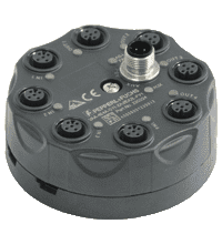
G2 flat module
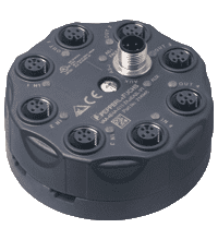
G4 module IP65
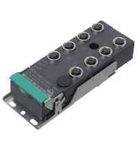
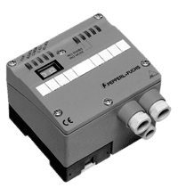
Cabinet module
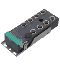
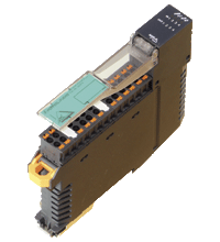
Cabinet module
- AS-Interface certificate
- Degree of protection IP67
- Flat or round cable connection (via standardized EMS base, not included with delivery)
- Cable piercing method for flat cable
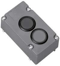
- 2 integrated illuminated pushbuttons
- Variable colors
- AS-Interface certificate
- AS-Interface connection via flat cable and EMS standard bottom section (included delivery)
- Degree of protection IP65
- Voltage supply from AS-Interface
- Connection to PROFIBUS DP
- Commissioning, without PROFIBUS communication
- All AS-Interface functions possible via PROFIBUS
- PLC functionality
- Error diagnostics via LEDs and LC display
- Parameterization and monitor software
- AS-Interface certificate
- PELV/SELV
- LED operating display
- 8 A output load
- 115 V AC / 230 V AC switchable
- AS-Interface data decoupling
- Overload protection using FUSE mode
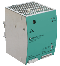
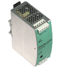
PLC Power Supply
- Up to 2.8 A output load
- Power factor correction
- Electronic overload protection and display
- LED operating display
- AS-Interface data decoupling
- PELV/SELV
- NEC Class 2 Power Supply
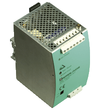
PLC Power Supply
- Up to 4 A output load
- LED operating display
- 100 V AC up to 240 V AC
- AS-Interface filter integrated
- Earth fault detection
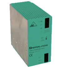
- 8 A output load
- 200 ... 500 VAC
- SELV
- LED operating display
- AS-Interface data decoupling
- Power factor correction
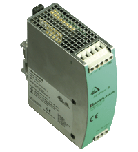
- Output current max. 4 A
- PELV
- Input voltage 24 V DC
- LED operating display
- 90.5 % efficiency level
- Up to 4 A output load
- Multiple AS-Interface networks can be operated through a single power stage
- Suitable for double master without data uncoupling
- Housing with removable terminals
- LEDs for display of AS-Interface voltage
- Minimum delay of signal
- Line lengthening by 100 m (max. 2 repeater in series)
- Galvanic isolation between AS-Interface circuits 1 and 2
- No parameterization
- Need no specific address on the AS-Interface bus
- Base for flat cable included in delivery
- Minimum delay of signal
- Line lengthening by 100 m (max. 2 repeater in series)
- Galvanic isolation between AS-Interface segments A and B
- No parameterization
- Need no specific address on the AS-Interface bus
- Housing with removable terminals
- The integrated terminator permits up to 200 m network lengths on Segment A
