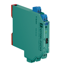
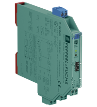
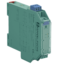
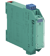
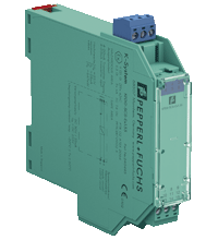
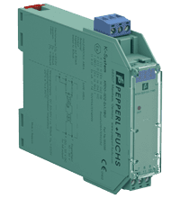
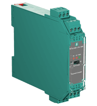
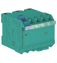
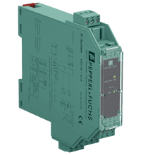
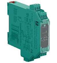
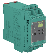
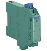
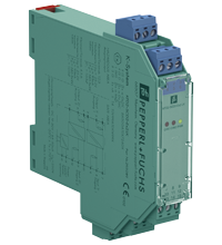
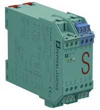
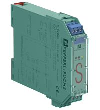
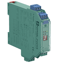
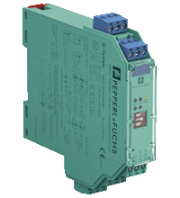
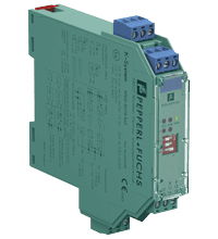
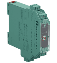
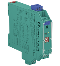
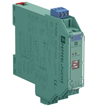
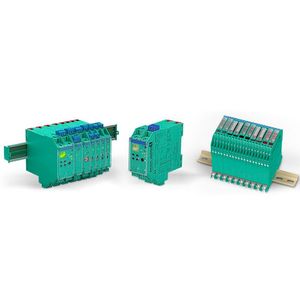
Pepperl+Fuchs K-System
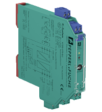
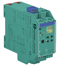
- 1-channel isolated barrier
- 24 V DC supply (Power Rail)
- Thermocouple, RTD, potentiometer or voltage input
- Current output 0/4 mA ... 20 mA
- Sink or source mode
- Configurable by PACTware
- Line fault (LFD) and sensor burnout detection
- Up to SIL 2 acc. to IEC 61508/IEC 61511
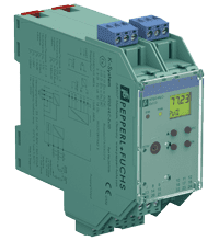
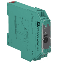
- 1-channel isolated barrier
- 24 V DC supply (Power Rail)
- HART field device input with transmitter power supply
- Usable as signal splitter (1 input and several outputs)
- 3 analog outputs 4 mA ... 20 mA
- Sink and source mode output
- Configurable by keypad
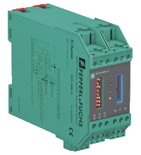
- 16-channel
- 24 V DC supply (Power Rail)
- HART field device input (revision 5 to 7)
- Up to 15 KFD0-HMS-16 slave units can be connected
- Up to SIL3 acc. to IEC 61508
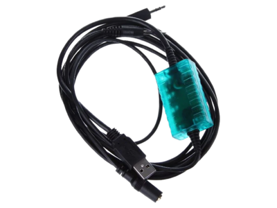
- Isolated USB interface cable
- Used with K-, E- and H-System devices
- Used with PACTware
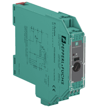
- 2-channel isolated barrier
- 24 V DC supply (Power Rail)
- Analog input (AI), Analog output (AO)
- Operates as transmitter power supply or current driver
- Housing width 12.5 mm
- Up to SIL 2 (SC 3) acc. to IEC/EN 61508
- 1-channel isolated barrier
- 24 V DC supply (Power Rail)
- Dry contact or NAMUR inputs
- Relay contact output
- Line fault detection (LFD)
- Housing width 12.5 mm
- Up to SIL 2 (SC 3) acc. to IEC/EN 61508
1-channel isolated barrier
24 V DC supply (loop powered)
1-channel isolated barrier
24 V DC supply (loop powered)
Current input/output 0 mA ... 40 mA
1-channel isolated barrier
24 V DC supply (loop powered)
Current input/output 4 mA ... 20 mA
1-channel isolated barrier
24 V DC supply (loop powered)
Output: 24 ... 26 V/400 mA
Couples PROFIBUS PA devices transparently to PROFIBUS DP
High-power trunk for high device count and long cable lengths
- Output: 12.6 ... 13.4 V/100 mA
- Couples PROFIBUS PA devices transparently to PROFIBUS DP
- Intrinsically safe, Ex ia (FISCO or Entity)
- Installation in Zone 2/Class I, Div. 2
- Fixed, high-availability terminator
- For all non-redundant masters
- Cyclic/acyclic data exchange
1-channel isolated barrier
24 V DC supply (Power Rail)
Input 2-wire and 3-wire transmitters and 2-wire current sources
Interface for Power Rail
Supply current le- 4 A
Interface for Power Rail
Used for redundant configuration
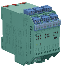
- 16-channel isolated barrier
- 24 V DC supply (Power Rail)
- Analog or digtial field device inputs
- Monitors leakage current
- Fault relay contact output
- LED status indication
- Test circuit for validation
- Parallel connection for easy integration
- Conformal coating
1-channel signal conditioner
24 V DC supply (Power Rail)
- 1-channel signal conditioner
- 24 V DC supply (Power Rail)
- Current and voltage input
- 2 relay contact outputs
- Programmable high/low alarm
- Configurable via DIP switches and potentiometer
- Terminal blocks with test sockets
- 1-channel signal conditioner
- 24 V DC supply (Power Rail)
- Thermocouple, RTD, potentiometer or voltage input
- Redundant TC input
- Current output 0/4 mA ... 20 mA
- 2 relay contact outputs
- Configurable by PACTware or keypad
- Line fault (LFD) and sensor burnout detection
- Up to SIL 2 acc. to IEC 61508/IEC 61511
1-channel isolated barrier
24 V DC supply (Power Rail)
2-channel isolated barrier
24 V DC supply (Power Rail)
1-channel isolated barrier
24 V DC supply (Power Rail)
1-channel isolated barrier
24 V DC supply (Power Rail)
2-channel isolated barrier
24 V DC supply (Power Rail)
2-channel isolated barrier
24 V DC supply (Power Rail)
2-channel isolated barrier
24 V DC supply (Power Rail)
2-channel signal conditioner
24 V DC supply
PNP/push-pull, dry contacts or NAMUR inputs
- 1-channel isolated barrier
- 24 V DC supply (Power Rail)
1-channel isolated barrier
24 V DC supply (Power Rail)
Dry contact or NAMUR inputs
Pepperl+Fuchs is a world-renowned manufacturer of industrial electronics. The company keeps up with the times and provides various explosion protection solutions. In particular, in our today's material, we will study in more detail the Pepperl+Fuchs K-System.
Features and Benefits of the Pepperl+Fuchs K-System
IS barriers are used to protect intrinsically safe circuits in hazardous areas. In addition to the necessary current and voltage limitations, IS barriers have additional electrical isolation between the excitation and control circuits.
K-System consists of various IS barriers that can be mounted on a 35 mm DIN rail. The K-System is convenient in specification selection, integration, and expansion. The wide range of IS isolators for use in hazardous areas includes more than 150 models, each with innovative features and benefits.
And among the features and advantages of the K-System, the following can be distinguished.
- Hazardous area certification.
- Intrinsic safety.
- Compact design.
- Easy installation.
- Flexibility.
- Modular building.
- Вiagnostic capabilities.
- Safety.
- cost-effectiveness.
- Compliance.
- Reliability.
- Process optimization.
- Adaptability.
Products and Solutions Offered by the Pepperl+Fuchs K-System
The K-System includes many different positions that form intrinsic safety barriers. Let's find out which products are included in this list.
Switch Amplifiers
Isolator switches supply power to a proximity switch in a hazardous area, accept proportional current, convert input signals to digital output signals, and transmit switching signals to a control device such as a DCS or PLC.
Frequency converters
Frequency converters repeat and convert the input frequency of various hazardous area signals (mechanical contact, proximity switch, magnetic sensor, voltage, or current level) into a safe area.
Solenoid Drivers
Solenoid drivers are used in many applications to provide linear or rotary actuation in mechanical systems.
Relay modules
The relay module switches circuits inside the hazardous area. It can be used to determine external on/off conditions and to control various external devices.
Transmitter power supplies
Transmitter power supplies supply and supply 4-20 mA signals from standard or SMART transmitters in hazardous areas. They transmit an isolated signal proportional to a measured value, such as temperature, pressure, or flow, from dangerous to safe spaces.
Repeaters
Isolated repeaters transmit and isolate signals from hazardous areas to safe areas. They send the following signals: mV signals from thermocouples and strain gauges, 0-10 V signals, voltage pulses, resistance from RTDs, and potentiometers.
Signal Converters
K-System signal conditioners consist of transmitters that receive signals from devices for hazardous areas, i.e., temperature sensors, potentiometers, or strain gauges, and then convert and process them into signals such as 0/4-20 mA or 0/2-10 V.
Trip Amplifiers
Trip amplifiers monitor temperature, flow, level, pressure, or frequency limits. They can monitor high (MAX) or low (MIN) alarms with selectable operating modes and hysteresis. Emergency shutdown or alarm can be initiated using the alarm output.
SC-System
SC-System signal conditioners are specifically designed for general-purpose applications and provide reliable process communication. High-quality insulation, extended temperature range, and compact housing design characterize the signal converter range.
Applications and Industries
Let’s discover some industries and applications where the Pepperl+Fuchs K-System is commonly used.
- Oil and gas. The oil and gas industry has many hazardous areas, such as oil rigs, refineries, and chemical processing plants. The K-System provides intrinsic safety for sensors, control equipment, and communication devices in these environments.
- Chemical processing. Chemical plants often handle volatile substances, making intrinsic safety essential for all electrical and electronic components used in production.
- Pharmaceuticals. Pharmaceutical manufacturing facilities deal with potentially flammable substances and require intrinsically safe equipment to ensure safety during the production and handling of pharmaceutical products.
- Mining. In underground mines and other mining operations, flammable gases and dust make intrinsic safety crucial for electrical and electronic equipment.
- Petrochemicals. Petrochemical plants and facilities dealing with petrochemical products require using intrinsically safe devices to minimize the risk of explosions and fires.
- Food and beverage. Some food and beverage processing environments involve the handling of flammable materials, making intrinsic safety necessary for specific equipment.
- Water and wastewater. Water and wastewater treatment facilities may have areas with explosive atmospheres due to the presence of gases, which necessitates the use of intrinsically safe devices.
- Automotive. In automotive manufacturing, specific processes involving volatile substances may require using intrinsically safe equipment.
- Paints and coatings. The paint and coatings industry often deals with flammable solvents, making intrinsic safety critical for various equipment used in the production process.
- Agriculture. Specific agricultural processes may involve hazardous materials, and intrinsic safety solutions can be employed for safety in these applications.
- Power generation. Power plants, especially those using fossil fuels, need intrinsic safety measures to protect against potential explosions in critical areas.
- Marine. Intrinsic safety solutions are utilized in marine environments where flammable gases and vapors might be present.
Installation and Maintenance Guidelines for the Pepperl+Fuchs K-System
Now let's look at short installing and maintaining Pepperl+Fuchs K-System manual.
- Ensure all K-System products you plan to install have the required certifications and meet the safety standards of the hazardous area applications in which they will be used.
- Clearly define and understand the danger zones in your facility. Install K-System products only in the hazardous areas for which they are intended.
- Use certified intrinsically safe cables and installation wiring to ensure inherently safe integrity. Avoid using unapproved components or methods that may compromise the installation's security.
- Proper grounding and connection of equipment is essential in hazardous areas. Follow the manufacturer's recommendations for grounding and provide low-resistance connections.
- Separate intrinsically safe and non-intrinsically safe circuits to avoid potential safety hazards.
- When using IS barriers, ensure they are installed following the manufacturer's instructions and compatible with the devices they protect.
- Perform routine inspections of K-System equipment for physical damage, loose connections, or any signs of wear.
- Follow the manufacturer's recommended calibration and test schedule for all intrinsically safe devices to ensure accurate and reliable performance.
- Monitor and correct any environmental factors affecting equipment performance, such as temperature, humidity, and exposure to corrosive substances.
- Maintain complete installation, maintenance, and test documentation for regulatory compliance and troubleshooting.
- Allow only qualified and trained personnel to install, maintain or repair K-System equipment to ensure safety and proper function.
- If replacement parts are required, use original manufacturer-approved components to ensure intrinsic safety and system certifications.
