How to Select the Right Encoder Resolution for Industrial Applications
23.09.2026
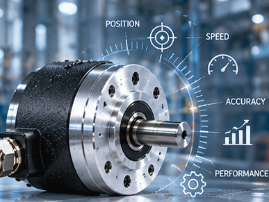
In industrial automation and drive technology, the selection of measuring components is often fraught with misconceptions. Among all the technical characteristics of feedback sensors, encoder resolution is the most common cause of errors in motion control system design. There's a persistent myth that the maximum available value of this parameter automatically guarantees the highest equipment accuracy. However, in practice, excessive resolution unnecessarily increases project costs and can directly cause control loop instability, controller hardware failures, and emergency shutdowns of the production line.
Selecting the optimal number of measurement steps requires the engineer to have a comprehensive understanding of machine mechanics, communication channel bandwidth, and the computational limitations of the control electronics. This parameter directly impacts the smoothness of speed control, dynamic positioning error, noise filtering algorithms in PID controllers, and the final cost of the automation system.
Today we'll cover:
- What encoder resolution means and how it affects machine performance;
- How pulses per revolution (PPR) influence positioning accuracy and speed feedback;
- Why selecting excessive resolution can create control system problems;
- Recommended resolution ranges for conveyors, servo systems, robotics, and CNC machines;
- Includes calculation examples, comparison tables, and practical engineering recommendations.
What Is Encoder Resolution?
Encoder resolution refers to the number of measurement increments generated during one shaft revolution, determining how accurately a motion control system can detect speed and position changes.
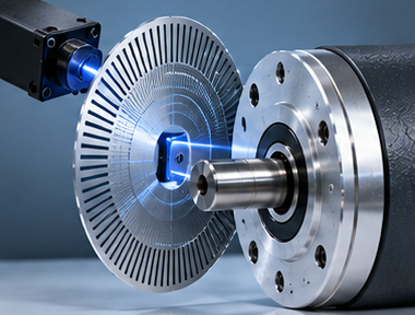
For incremental devices, this parameter is traditionally expressed as the number of pulses per revolution. This value strictly defines the minimum angle of rotation that can be physically detected and recorded by the controller. The higher this value, the smaller the measurement disk's circumference is divided into.
In industrial drive architecture, this parameter sets the basic sensitivity limit of the entire automation system. If a mechanical unit moves by an angle smaller than the step of one pulse, the control processor simply will not receive information about the position change and will not be able to provide corrective action to the motor.
Why Encoder Resolution Matters
The overall stability and dynamics of the motion control loop depend on the correct selection of the encoder resolution. When this parameter is chosen correctly, the system ensures perfect repeatability of operations, minimizes dynamic errors when changing rotation directions, and guarantees a uniform technological process. In speed control loops, the feedback sensor supplies data for calculating the position derivative, and if the information is insufficient, the algorithm begins to operate discretely, causing jerking and increased wear on mechanical transmissions.
The value of resolution is directly related to the concept of encoder accuracy, but they should never be confused. Resolution indicates the number of digital divisions, while actual accuracy includes manufacturing errors of the optical disk, bearing play, temperature drift of components, and mounting eccentricity. Insufficient resolution leads to quantization noise in the PID controller: the controller detects speed deviations too late and generates an excessive compensating current pulse to the motor, leading to self-oscillations and overheating of the windings.
Field insight: “The goal isn’t to buy the highest-resolution encoder available. The goal is to buy the resolution that matches the application’s actual needs”
Understanding Pulses Per Revolution (PPR)
For incremental encoders, the basic unit of resolution is the encoder pulses per revolution, abbreviated as PPR in technical documentation. This metric physically reflects the number of rectangular electrical pulses the device generates on one main channel during a full 360-degree shaft rotation. Inside the encoder, an optical disk with alternating transparent and opaque sectors interrupts the light beam, thereby generating a primary analog signal, which is then converted by a built-in comparator into a clear digital square wave.
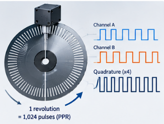
To expand data acquisition capabilities in industrial electronics, the concept of quadrature counting is widely used. The encoder outputs not one, but two independent signal channels, phase-shifted by ninety electrical degrees relative to each other. This allows the controller to accurately determine the direction of shaft rotation based on which channel leads the other, and programmatically increase the initial encoder PPR by two or four times, while simultaneously recording every rising and falling edge of the pulse. There are several categories:
- 100 PPR. Required exclusively for rough speed monitoring of massive, low-speed shafts, conveyor drums, or auxiliary pump units, where an angular increment of 3.6 degrees is sufficient to capture speed, and the minimal data flow does not overload the processor;
- 500 PPR. Standard for ventilation systems, simple conveyors, and lifting mechanisms, as it provides stable speed monitoring of asynchronous motors in a range of up to 3,000 rpm with a resolution of 0.72°;
- 1024 PPR. A universal industrial solution for most standard packaging machines, pumping stations, and general-purpose drive systems, it guarantees an optimal balance between measurement error (approximately 0.35°) and the stability of the PID speed controller;
- 2048 PPR. It is widely used in feedback loops of modern servo drives, medium-precision coordinate tables, and automated dispensers, where X4 quadrature processing achieves a control depth of 8192 steps per revolution, eliminating motor jerking at low speeds;
- 5000+ PPR. It is also used in precision industrial equipment such as multi-axis robotic manipulators, heavy-duty CNC gantry machines, and laboratory measurement benches, where micro-movements of less than 0.05° must be recorded, using specialized high-frequency signal processors.
How Resolution Affects Position Accuracy
Higher encoder resolution allows smaller position changes to be detected, improving positioning accuracy and machine repeatability.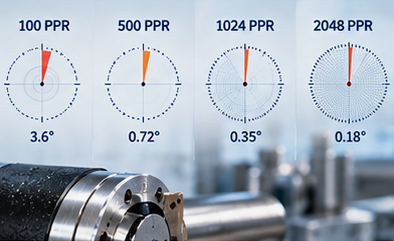
The discreteness of the measuring steps severely limits the ultimate accuracy of tracking the spatial coordinate of the mechanism. As the shaft rotates, the controller continuously sums the incoming signals and converts the digital code into linear millimeters or angular degrees. The smaller the physical size of a single increment, the more accurately the positioning system can stop the moving carriage or manipulator arm at a given point, ensuring constant encoder positioning accuracy of the actuator.
The influence of sensor parameters on the system kinematics is characterized by the following factors:
- Increment size. A smaller sampling step significantly improves continuous tracking of the current coordinate of the machine's working parts;
- Angular dependence. The relationship between the shaft's full mechanical revolution and the resolution determines the minimum sector of a circle that can be physically captured by the controller.
To accurately calculate the minimum angular displacement that the sensor can register on its main measuring channel, engineers use the following mathematical formula:
Angular Resolution = 360° ÷ PPR
When the controller switches to X4 quadrature signal processing mode, the resulting angular resolution is further reduced by a factor of four, allowing for tracking of micro-displacements of the actuator.
The table below clearly shows how the angular size of one discrete step on the main channel changes depending on the selected sensor rating:
Encoder Resolution | Angular Resolution |
100 PPR | 3.6° |
500 PPR | 0.72° |
1024 PPR | 0.35° |
2048 PPR | 0.18° |
How Resolution Affects Speed Measurement
The quality and stability of the speed control loop directly depend on how frequently and regularly the control processor receives motion information. The controller calculates the current rotation speed using two methods: by counting the number of incoming pulses over a fixed period of time or by measuring the duration of the time interval between two adjacent signal edges. The choice of resolution determines which of these methods will be more effective in a specific speed range.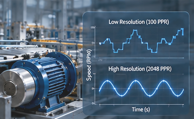
With low dynamic requirements, a modest resolution has its advantages:
- Reduced computational load. The controller processor processes infrequent interrupts, freeing up resources for executing the main logic program;
- Noise immunity. Infrequent, long-duration pulses are less susceptible to distortion due to high-frequency electromagnetic interference.
If a high-tech motion control encoder is installed on the object, the system receives a dense stream of measurement information, which dramatically changes the drive's behavior:
- Smoothness at low speeds. The controller instantly detects the slightest shaft jamming or load change at speeds close to zero, and promptly adjusts the winding current.
- High PID channel response. Minimal waiting time for the next pulse allows for higher controller gains, while making the drive extremely responsive to dynamic disturbances.
These properties are critical for variable-frequency asynchronous drives, synchronized conveyor systems, and precision actuators.
Can Encoder Resolution Be Too High?
The desire to install a sensor with the highest possible pulse rate often leads to serious technical problems and unnecessary costs. The primary limitation is the maximum pulse repetition rate that the sensor's output stages can physically generate and that the PLC counter input boards can process. Multiplying the maximum motor shaft speed by the sensor's resolution yields the signal's operating frequency, measured in kilohertz or megahertz.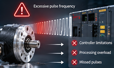
If this frequency exceeds the receiver's hardware limitations, dangerous failures begin to occur in the system:
- Skipped measurement pulses. Due to the controller's input optocoupler's finite switching time, some signals are lost, causing the accumulation of an unrecoverable coordinate error;
- CPU overload. Hardware interrupts from the high-speed counter begin to be generated so frequently that the PLC has no time to execute the cyclic control program;
- Decreased noise immunity. Ultra-short high-frequency pulses begin to merge with parasitic capacitive interference in a long cable, making it impossible to filter the useful signal.
Field insight: “One of the most common mistakes I see is selecting a very high-resolution encoder for an application that gains no practical benefit from it”.
Recommended Encoder Resolutions by Application
Each type of industrial equipment is different from the others in terms of physical characteristics, including how they perform in terms of motion, accuracy, and tolerance. Based on our experience operating in the field, most applications do not require high-end sensors; rather, reliable sensors developed by manufacturers will typically meet the needs of their users.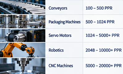
Below is a recommended resolution range for various types of industrial machines:
Application | Typical Resolution |
Conveyor Systems | 100-500 PPR |
Packaging Machines | 500-1024 PPR |
Servo Motors | 1024-5000+ PPR |
Robotics | 2048-10 000+ PPR |
CNC Machines | 5000-20 000+ PPR |
Differences in requirements are due to the rigidity of the kinematic transmissions. On a conveyor belt, which uses an elastic belt and a massive gearbox with significant backlash, high resolution is pointless, as the mechanics are physically incapable of handling micron-scale movements. In contrast, robotics and CNC machines use backlash-free harmonic gearboxes and ball screws, which can translate the high resolution of a sensor into realistic tool movement accuracy.
Incremental vs Absolute Encoder Resolution
Fundamental differences in the physical method of encoding shaft spatial position information impact how the control system specifies and processes the device's resolution.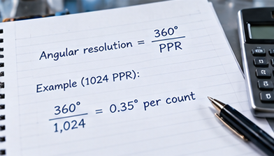
Incremental encoders
In these devices, feedback is based solely on continuous pulse counting relative to a certain starting point. The designer selects a fixed value, where the incremental encoder resolution is specified in PPR and remains constant over the entire operating range. These encoders are the most cost-effective, easy-to-connect, and widely used solution. However, they completely lose information about the current position when the power supply is suddenly interrupted and require a homing procedure each time the system is restarted.
Absolute encoders
These encoders do not generate continuous pulse trains, but instead provide a unique code address for each fixed shaft rotation angle via a digital communication protocol. Here, absolute encoder resolution is measured not in pulses, but in bits, where the number of unique positions per revolution is equivalent to two raised to the power equal to the number of bits. These encoders instantly restore their position after power is applied, without the need for any adjustment movements. Their design is divided into single-turn and multi-turn versions, which can additionally count the number of complete shaft revolutions using an integrated system of miniature mechanical gears.
Let's compare the characteristics of the two technologies:
Feature | Incremental | Absolute |
Resolution Format | PPR | Bits |
Power-Loss Recovery | No | Yes |
Position Tracking | Relative | Absolute |
Factors I Consider Before Choosing Encoder Resolution
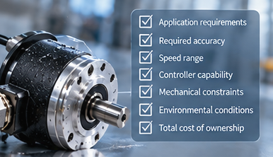
When designing your next industrial system, never make a decision in isolation, based solely on bare numbers from a catalog. There is a complex set of interrelated factors that determine how to choose an encoder resolution for a specific technical object without the risk of making a critical error:
- Required positioning accuracy. You need to base it on the manufacturing tolerance of the finished product or movement, while converting linear microns into angular seconds on the motor shaft;
- Maximum speed. High speeds force you to strictly correlate the number of pulses with the frequency response of the signal receiver's input stages;
- Controller computational limits. You need to study the specifications of the PLC high-speed counter module in advance to ensure the encoder frequency does not exceed its hardware scanning limit;
- Kinematic gear ratio. The presence of a reduction gearbox or ball screw dramatically increases the final resolution on the end effector, allowing you to choose a more modest and affordable encoder on the motor itself;
- Economic feasibility. The cost of a sensor increases nonlinearly with its parameters, so you should strictly justify any extra cost for excess bits or pulses based on process requirements.
- Environmental conditions. Strong magnetic fields produced by welding stations or an excessively high level of dust may make it impossible for a high-resolution optical sensor to function properly; in this situation, you would choose to use a robust, average-resolution (magnetic) sensor instead.
Real-World Examples
To see more distinctly how utilizing theory calculations can assist in designing a real-world solution, let's look at some practical examples of engineering in terms of modernizing and creating industrial equipment.
Conveyor speed monitoring
At a processing facility, where crushed stone is transported via a main belt conveyor, the amount of material that is being fed onto the conveyor belt is continuously regulated based on the load on that unit. The mechanical unit being utilized to drive the conveyor belt is composed of an asynchronous electric motor, a large worm gear, and a drive drum. Due to the amount of weight (load) on this conveyor belt and the need to provide a smooth feed of material onto the conveyor belt, a sensor with a resolution of 250 pulses per revolution was sufficient for the frequency converter to operate stably and the elasticity of the rubber belt combined with the natural gear backlash within the worm gear imposed limits to implementing any measuring devices with a greater level of precision.
Packaging machine synchronization
As a part of a confectionery packaging line, a rotary cutter blade must accurately make contact with a photometric mark printed on a continuously moving polymer film, at a line speed of about three packages per second. To do this, the optical device selected was a 1024 PPR that allows for sufficient resolution to provide the control system with instant notification of any film/paper slipping, and make micro-adjustments to the drive algorithm without overloading the signal processor within the controller.
Servo motor applications
In a project to automate a five-axis robotic manipulator performing laser spot welding of car body parts, it was crucial to ensure absolute smoothness of the welding head's movement at ultra-low speeds. The slightest jerk would result in burn-through of the thin metal. A precision servo motor encoder with a resolution of 4096 PPR was installed on each articulated unit. Quadrature counting allowed the effective resolution to be increased to over 16 000 steps per revolution, providing ideal feedback for the servo motor's current loop.
CNC positioning systems
When upgrading a gantry milling machine for machining hardened steel molds, it was necessary to achieve positioning accuracy along the X and Y axes down to a few microns. Direct drive of the axes was achieved via high-precision ground ball screws without intermediate gearboxes. To achieve this, heavy-duty optical sensors with a physical resolution of 10 000 PPR were used. This high step density fully compensated for the screw's thermal expansion and ensured stable operation of the machine during finish milling of complex spatial surfaces.
Common Resolution Selection Mistakes

Engineering practice often encounters the consequences of incorrect design decisions caused by a superficial analysis of machine kinematics or blind adherence to the principle of redundancy:
- Selection of parameters solely based on accuracy. Designers forget that mechanical play in a coupling or gearbox can be tens of times greater than the sensor pitch, rendering high resolution completely useless;
- Ignoring hardware limits. Installing a sensor with a high PPR on a high-speed motor without checking the maximum input frequency of the PLC counter leads to an immediate loss of counting during acceleration;
- Errors in gear ratio calculations. The fact that the gearbox itself is a resolution multiplier for the final actuator of the system is ignored;
- Blind faith in performance improvement. The assumption that replacing a serviceable sensor with a model with a high PPR will automatically solve machine vibration problems, when the true cause lies in poor mechanical shaft balancing.
Let's consider the typical manifestations of these errors:
Problem | Possible Cause |
Unstable feedback | Excessive pulse rate |
Poor positioning | Resolution too low |
Missed counts | Controller limitations |
High cost without benefit | Overspecified encoder |
How I Choose Encoder Resolution
Your approach to solving this problem should always be based on rigorous back-calculation, starting from the final mechanical link and ending with verification of the electrical interfaces. This industrial encoder selection method guarantees the avoidance of system stability issues and optimizes the budget.
First, you should carefully study the specifications for the linear or angular travel of the machine's end-effector required by the customer. Then, once you know the lead screw pitch or gear ratio, you need to convert this value to the minimum required rotation angle of the shaft on which the encoder will be mounted. Multiply the resulting value by a safety factor of at least two or four – this is necessary to ensure the PID controller has room to maneuver and can handle errors before they exceed the process tolerance. Finally, be sure to multiply the selected PPR by the maximum rotation speed and compare the resulting frequency with the PLC's technical capabilities.
Expert insight: “I always start with the accuracy requirement and work backward. In many applications, a properly selected 1024 PPR encoder performs just as well as a much more expensive high-resolution model”.
Frequently Asked Questions
What is encoder resolution?
Encoder resolution is the number of measurement increments an encoder produces during one shaft revolution. It determines the minimum angle of rotation that the encoder can physically register and convert into a digital signal for subsequent processing by the controller.
Is higher encoder resolution always better?
No. Excessively high resolution can increase system complexity, controller load, and cost without improving application performance. Moreover, when the frequency limit of PLC input boards is exceeded, excessive resolution leads to missed pulses and critical positioning failures.
What PPR is suitable for conveyors?
Most conveyor systems operate effectively with encoder resolutions between 100 and 500 PPR. Due to backlash in gearboxes and natural slippage of the conveyor belt, using encoders with higher resolutions is economically and technically impractical.
What resolution is needed for servo motors?
Servo applications commonly use 1024 to 5000+ PPR, depending on precision requirements. High values are necessary here for positioning and to ensure ideal smoothness of speed control in the feedback loop at low speeds.
How does resolution affect positioning accuracy?
Higher resolution allows smaller position changes to be detected, improving positioning precision and repeatability. It reduces the quantization step and allows the control system to respond to micro-movements of the actuator and maintain it in precisely defined spatial coordinates.

Author: Caroline Karol
Chief Sales Officer of Eltra Trade s.r.o.