Norgren Pneumatic Cylinders: Types and How to Choose the Right One
29.10.2026
Pneumatic actuators convert compressed air energy into mechanical linear motion. In manufacturing processes, these devices perform a wide range of tasks: pushing, pulling, lifting, clamping, positioning, and transferring parts between process stations. The reliability of the entire automated system depends directly on the correct selection of each pneumatic drive component.
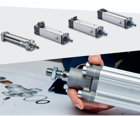
The industrial Norgren cylinders are recognized for their exceptional performance by virtue of high reliability, quality manufacturing, and a wide range of products. When designing a pneumatic system, it is essential to address main technical questions:
- What force is required to reliably move the load across all operating modes?
- What is the precise travel distance required for the actuator's working element?
- How much space is allocated for the actuator within the machine housing?
- How will the actuator body and piston rod be mounted to the machine frame?
A detailed analysis of these operational factors enables the selection of reliable Norgren air cylinders that ensure a long service life without the risk of premature wear. Furthermore, understanding the system's overall requirements helps determine whether standard Norgren pneumatic actuators are suitable or if specialized rodless mechanisms would be more appropriate.
How Does a Norgren Pneumatic Cylinder Work?
The operating principle of a pneumatic cylinder is based on fundamental laws of thermodynamics and fluid mechanics. Compressed air enters the working chamber, causing the piston to move and resulting in mechanical motion.
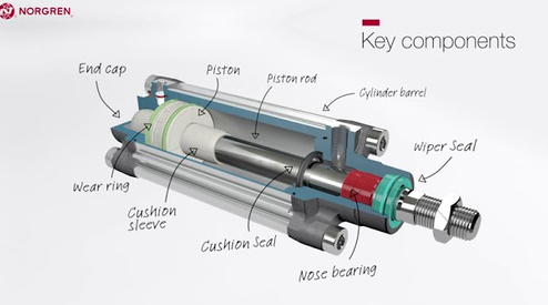
As the compressed air goes into the working chamber from the supply port, it occupies the volume within and creates the same pressure on the surface of the piston. The pressure force provides the linear force necessary to overcome static friction, inertia of mass, mechanical resistance, and external load. The piston moves along the polished inner surface of the cylinder under the action of the pressure. The piston rod is connected to the piston, passes through the front guide bushing, and transmits the generated force to the actuating mechanism of the machine.
The theoretical force generated by the device is determined by the fundamental relationship between pressure and area:
Force = Pressure × Piston area
Although this formula yields the ideal force value, the actual force available in a real-world pneumatic system is always lower than the theoretical figure. Dynamic friction from the elastomeric piston and rod seals reduces the resulting force. Additionally, pressure drops occur across fitting orifices, directional control valves, manifold blocks, flow control valves, and supply lines – particularly during high-speed cycling. For this reason, a safety factor is always applied during calculations.
Main Types of Norgren Pneumatic Cylinders
Depending on the nature of the required movement, the load magnitude, the available installation space, and the operating conditions, various pneumatic cylinder types are used; these differ in terms of internal design, dimensions, air supply method, and the principle of returning to the initial position.
Single acting cylinders
A classic single acting pneumatic cylinder uses compressed air to generate working force in only one direction – typically during rod extension. Compressed air is supplied through a single pneumatic port into the piston chamber. The piston and rod return to their initial position via an integrated mechanical spring or an external return load.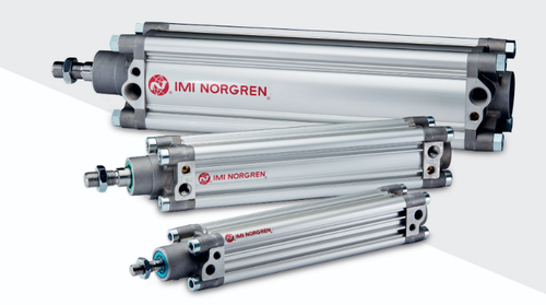
Since compressed air is consumed during only one half of the operating cycle, single-acting actuators offer reduced air consumption. They are widely used for simple process operations:
- Clamping. Securing parts in assembly fixtures and tooling;
- Ejection. Removing finished products from dies and molds;
- Positioning. Briefly stopping or holding items on a conveyor;
- Lifting and pressing. Unidirectional lifting of light loads or press-fitting operations.
When calculating the force for single-acting devices, it is important to account for the fact that the integrated spring creates constant resistance to the piston's forward movement. As the spring compresses toward the end of the stroke, its resistance increases, thereby reducing the effective output force.
Double acting cylinders
A versatile double acting pneumatic cylinder provides full pneumatic motion control during both the extend and retract strokes. The unit features two independent connection ports located in the front and rear end caps. Supplying compressed air to the piston-side chamber causes the rod to extend, while air from the rod-side chamber is exhausted to the atmosphere. Switching the directional control valve routes air to the rod-side chamber, forcing the piston to retract.
This bidirectional pneumatic control makes these devices a primary choice in industrial automation. They deliver high repeatability and force for demanding operations:
- Pushing and pulling. Bidirectional movement of heavy assemblies and working components;
- Cyclic processes. High-speed repetitive operations on packaging lines;
- Precise positioning. Control of grippers, guides, robotic modules, and dampers;
- Automatic loading. Feeding workpieces into machine work zones.
Double-acting cylinders allow for precise speed regulation in both directions and utilize built-in cushioning to dissipate kinetic energy at the end of the stroke.
Norgren Cylinder Designs for Different Applications
In addition to classification by operating principle, linear pneumatic actuators are categorized based on their housing design. The shape of the housing determines mechanical rigidity, dimensions, mounting methods, and resistance to external influences.
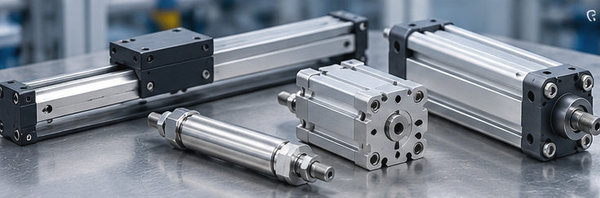
ISO and profile cylinders
Pneumatic cylinders manufactured according to international standards (ISO 15552, ISO 6432) feature strictly standardized mounting dimensions, thread types, center-to-center distances, and piston rod diameters. The profiled anodized aluminum barrel design, featuring concealed tie rods, prevents dirt accumulation and ensures high structural strength.
Standardization guarantees full interchangeability between units from different manufacturers, simplifying equipment maintenance and repair. These actuators are available in a wide range of piston diameters (from 32 to 320 mm) and stroke lengths. Slots in the barrel profile allow for the easy installation of magnetic position sensors without the need for additional mounting brackets.
Compact cylinders
When space within a machine is severely limited, Norgren compact cylinders deliver the required force with a significantly shorter axial length. Manufactured to the ISO 21287 standard, these compact actuators feature an optimized end-cap and piston design that reduces the unit's overall length by up to 50% compared to standard ISO cylinders of the same bore size.
These compact models are designed for short to medium stroke lengths. They are used in packaging machinery, electronic assembly systems, clamping devices, and test rigs – applications where a conventional cylinder would extend beyond the safety guards.
Roundline cylinders
Round pneumatic cylinders feature a smooth cylindrical body made of stainless steel or aluminum, with crimped or screwed-on end caps. Their round profile makes them suitable for installation in confined spaces.
These lightweight, reliable actuators are used in light machinery manufacturing, the food industry, pharmaceuticals, and packaging equipment. Their smooth exterior facilitates sanitation, while threaded front caps and rear clevis mounts offer flexibility in mounting options.
Rodless cylinders
A standard rod-style cylinder requires space equal to the body length plus the length of the extended rod. With long stroke lengths, the system's overall dimensions become excessive. To address this issue, Norgren rodless cylinders employ an internal piston mechanically or magnetically coupled to an external carriage that moves along the cylinder barrel.
The absence of an extending rod offers significant operational advantages:
- Space savings. The overall length of the actuator is only slightly greater than the working stroke;
- Long stroke. Capable of achieving working travel distances of several meters without the risk of rod buckling;
- Load handling. Integrated carriage guides can withstand high bending moments;
- Inter-machine transport. Automating part transfer over long distances and conveyor systems;
- Precision guidance. Ensures smooth movement of tools and feed units.
Bore Size, Pressure, and Cylinder Force
The proper sizing of the piston is a vital milestone in the design stage. The piston size affects the surface area available for the compressed air. Multiplying the piston area by the operating pressure of the system provides the theoretical value of force.
Force = Pressure × Piston area
The increase in the piston size results in a proportional increase of its surface area and consequently an increase in generated force at the same level of pressure. Also, an increase in the pressure of the supply line will also lead to the growth of the force. Still, the operating pressure is usually limited by the possibilities of the compressor.
Taking into consideration that for real-life applications the pneumatic system would lose pressure through pipes and face friction losses, the required value of force must never be equated to its theoretical value. The engineers take a safety margin – they choose the actuator that can produce 1.25-1.5 times the required load.
Also consider the difference between pushing and pulling forces in double-acting cylinders. When the rod extends, air acts upon the full piston area. During retraction, the presence of the rod reduces the effective piston area (calculated as the piston area minus the rod's cross-sectional area). Consequently, the pulling force is always lower than the pushing force at the same pressure.
Stroke Length and Installation Space
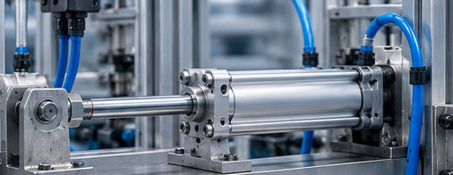
To correctly position the device within the machine, the unit's total dimensions across all operating positions must be taken into account.
A standard cylinder with a piston rod requires a total installation space comprising the body length, the extended rod length, and the clearance needed for fittings and mounting hardware. For instance, a cylinder with a 500 mm stroke might have a body length of 650 mm when retracted; when fully extended, the assembly's total length reaches 1150 mm. Failure to account for the rod's extension often leads to interference with safety guards or adjacent machine components.
Cylinder Speed and Airflow
Air pressure determines the force generated, while air flow rate determines the piston's travel speed. Pressure indicates whether the actuator can move the load, whereas flow rate determines how quickly the load traverses the working distance.
The following system elements influence speed:
- Flow control. Installing flow control valves with built-in check valves on the exhaust side allows for smooth speed regulation;
- Flow capacity. The flow coefficient of the directional control valve limits the maximum speed;
- Tubing diameter. The internal cross-section and length of pneumatic tubing create gas-dynamic resistance;
- Supply line pressure. Pressure stability prevents jerky movement;
- Chamber volume. Larger-diameter actuators require more air to fill the internal volume;
- Load mass. The inertia of the moving object determines acceleration and deceleration dynamics.
A larger-diameter actuator requires a significantly greater volume of air. If the flow cross-sections of the valves and tubing remain unchanged, a large cylinder will move more slowly than the original, smaller-diameter actuator.
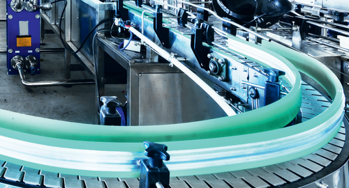
Mounting and Load Direction
Common mounting options include:
- Feet. Mounting feet for installation parallel to the machine bed surface;
- Flanges. Front or rear flanges for rigid attachment to bulkheads or mounting plates;
- Clevises and rod eyes. Rear pivot mounts for articulating or oscillating applications;
- Trunnions. Pivot trunnions for mounting along the cylinder barrel;
- Rod end bearings. Rod ends designed to compensate for minor angular misalignments.
If the piston rod is subjected to lateral radial loads or bending moments, increased friction occurs at the front bushing. If lateral forces cannot be eliminated, external linear guides or actuators with integrated guide rods should be used.
How to Choose a Norgren Pneumatic Cylinder
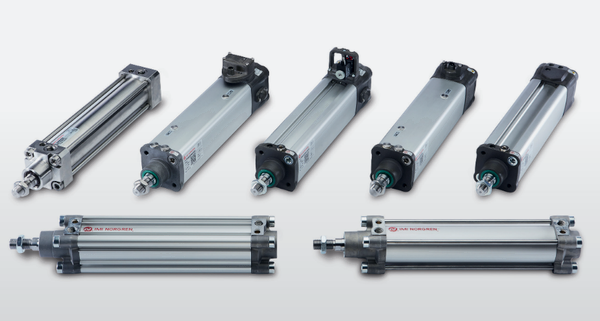
To determine how to choose a pneumatic cylinder for a specific task, we recommend using the checklist below for selecting Norgren pneumatic cylinders:
- Required movement. Determining the direction and nature of the load's movement;
- Single or double acting. Deciding whether pneumatic control is needed in one or both directions;
- Calculated force. Calculating the required force, including a safety margin;
- Operating pressure. Assessing the actual compressed air pressure directly at the actuator;
- Piston diameter. Selecting the diameter to generate the required pushing or pulling force;
- Stroke length. Determining the total working travel distance;
- Design configuration. Choosing between standard, compact, round-body, or rodless designs;
- Mounting space. Checking housing dimensions and rod extension at extreme positions;
- Movement speed. Calculating required airflow and valve flow capacity;
- Mounting method. Selecting appropriate flanges, clevises, foot mounts, or trunnions;
- Load direction. Avoiding side loads and bending moments on the piston rod;
- Cushioning. Selecting adjustable pneumatic cushioning to absorb inertia;
- Operating temperature. Considering ambient temperature and specific process requirements;
- Operating environment. Accounting for exposure to dust, moisture, chemicals, or regular equipment wash-downs;
- Position sensors. Determining the need for reed switches or proximity sensors.
Common Mistakes When Selecting a Pneumatic Cylinder
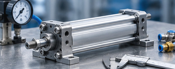
Pneumatic cylinder selection involves many factors; avoid these common design errors:
- Selecting diameter without calculation. Choosing the piston diameter without accounting for load mass and friction forces;
- Estimating based on line pressure. Using compressor pressure instead of the actual pressure at the cylinder;
- Lack of a safety margin. Calculating the actuator based solely on theoretical force without a safety factor;
- Stroke length errors. Ordering a unit with an incorrect stroke, leading to incomplete travel or overtravel;
- Ignoring rod extension. Failing to account for the total space required when the rod is fully extended;
- Undersizing air lines. Using valves and fittings with insufficient flow capacity;
- Allowing side loads. Omitting external guides when radial forces act on the rod;
- Incorrect mounting choice. Rigidly mounting the unit in oscillating linkage mechanisms;
- Lack of cushioning. Ignoring end-of-stroke cushioning when dealing with high speeds and masses;
- Neglecting protection. Installing standard seals in environments with aggressive chemicals or high temperatures;
- Replacing based only on size. Replacing a unit based solely on diameter and stroke without verifying cushioning requirements;
- Overlooking accessories. Ordering an actuator without the necessary mounting brackets and magnetic sensors.
Expert insight. When selecting a pneumatic cylinder, start with the load and movement. Calculate the required force, determine the stroke, and then check pressure, available space, speed, mounting, and operating conditions. Bore and stroke are important, but they aren’t enough on their own to identify the right cylinder.

Author: Caroline Karol
Chief Sales Officer of Eltra Trade s.r.o.