Turbine Flow Meter: Technology and Working Principle
30.06.2020
 CONTENTS:
- What is a turbine flow meter? Main parts
- How does it work?
- What is k factor in turbine flow meter?
- Turbine flow meter calibration
- How to install turbine flow meter? Installation guidelines
- Advantages and disadvantages
- Why do we use turbine flow meter?
What is a turbine flow meter? Main parts
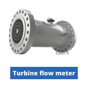
Turbine flow meter is a device for measuring the volumetric flow rate of gases or liquids passing through a pipeline per unit of time.
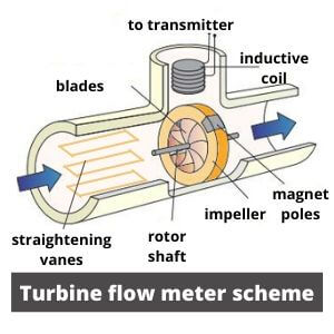
A simplified scheme of such flow meter consists of the 3 main parts:
- Turbine (rotor, impeller, blades)
- Pickup sensor (with transmitter)
- Housing
Turbine consists of a shaft, which is fixed in the pipeline and an impeller. Such impeller is multi-bladed wheel. That wheel is attached to a shaft that rotates on bearings. Each of blades has magnetic pole on its edge. All these parts form a rotor (moving part) of the turbine.
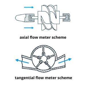
There are two main types of installation according to the flow technology: axial and tangential. In axial type, the flow is directed parallel to the shaft axis, while in tangential one it flows around the circumference. (Look at picture).
Material of the rotor and bearings is selected depending on the type of medium and required accuracy.
Pickup sensor system consists of an induction coil (or Hall sensor) and a signal transmitter (transducer). Induction coil generates electrical impulses in direct proportion to the rotor speed and transfers them to a recording device. Sometimes devices are equipped with two such coils to take measurements about the forward and reverse flow directions. The Hall sensor simply detects changes in magnetic fields.
Housing is made of non-magnetic cast steel (or aluminum or even plastic) and contains both a measuring sensor and a rotor. The most popular way of mounting is method with using flanges that coupled with pipeline.
Another important detail that is worth mentioning is straightening vanes. For this purpose, most often used plates that are installed in parallel with movement direction of medium. They are used to evenly distribute stream jets across all blades. In addition, mechanical stabilizers are mounted in the structure for avoiding a turbulence. By the way, the work of Vortex flowmeters is based on the special creation of that vortex.
How does it work?
The main purpose of turbine flowmeter is to measure the volumetric flow rate through flow velocity analysis. This principle is based on tracking multi bladed rotor rotation speed. So, how does a turbine flow meter work?
Such method is very similar to cycling. The faster you pedal, the faster you move. Flow of liquid or gas acts as a driving force and turbine rotor as the wheels. Let`s explain how a turbine flow meter works in detail.
Water or gas flows from a pipeline into a section with a turbine. First, straightening vanes separate the main flow into jets and direct it directly onto the blades.
Mechanical energy push on blades surfaces and makes them rotate. The larger volume of substance passing through pipeline, the more mechanical energy created, and the higher the angular (rotational) speed of the blades.
Blades with magnets on its edge pass near an electrical pickoff sensor at a certain speed and cause changes in magnetic fields. If the device has an induction coil, then an electric pulse is induced in it. If a Hall sensor is installed, it simply captures those changes. This method is similar to the magnetic flow meter.
Value of frequency with which these changes occur is monitored and sent to the transmitter. The frequency of such signals is directly proportional to the flow velocity.
Here is a turbine flow meter equation about dependence between volume flow and pulse frequency:
F= k * Q
Where:
F - The indicator that displays how many pulses the pickup sensor detects per minute or second
Q - Volumetric flow (m³, gallons, liters / s)
k - Special coefficient, also known as k-factor (for example, the number of pulses per m³). We consider it in more detail below.
Further, the transmitter analyzes the received data and converts them into an analog or digital signal.
What is k factor in turbine flow meter?
K-factor is a key coefficient that displays the number of pulses per unit volume or mass of the medium. This constant value includes main characteristics of substance and pipe (viscosity, temperature, diameter, etc.)
It is necessary for the correct display of values in measuring systems. After calibration, this coefficient is indicated in product certificate.
Turbine flow meter calibration
Calibration of the device is carried out in laboratory conditions on the water.
If the device is supposed to be used in a viscous medium (2-300 cSt, centistokes), liquids with properties similar to those of the working medium are taken for calibration.
As a result, for each purpose and medium its own K-factor is assigned. Sometimes, manufacturers add ready-made universal viscosity charts for calibration to its equipment kit. Using them, a user can quickly determine already calculated K-factor for different substances.
How to install turbine flow meter? Installation guidelines
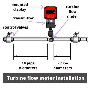
 Turbine flowmeter is installed only on straight sections or vertical and horizontal pipelines. There is an arrow on its housing indicating the desirable flow direction.
The length of straight section before single-turbine device should be at least 10 pipe diameters and at least 5 diameters after it. Dual turbine units can be installed on straight sections of shorter distance.
On a vertical pipeline, it is best to install the flowmeter so that the fluid flow is directed from top to bottom. In this case, air bubbles accidentally entering the device will quickly leave it.
If device need to work with contaminated media, it is worth mounting and additional filters to avoid damage to structure by solid particles.
Advantages and disadvantages
So, we considered turbine flow meter working principle and theory. It is time to definition about its main pros and cons.
Advantages:
- Easy installation and maintenance
- High accuracy, linearity and repeatability of results
- Optimal operation at high pressure (up to 400 bar)
- Large temperature range (–210°…+177°C / -346…+350,6° F)
- High throughput (suitable for diameters from 40 to 250 mm).
- Fast dynamic response and great sensitivity to changes
- Can work with substances with low conductivity
- Low pressure drop
- Low cost
Disadvantages:
- It is necessary to set the viscosity of the material before work
- Inability to operate in environments with high viscosity (where the flow profile is laminar
- Substances must be clean (no particulate parts)
- Air bubbles in fluid effects on accuracy
- Requires a long straight pipe section
- Not vibration resistant
Why do we use turbine flow meter?
Currently, about 7% of all users choose exactly turbine flow meters. So, how do they use it?
It is an excellent device for measuring very different types of medium:
- Water
- Air
- Natural gases
- Fuel
- Steam
- Vapor
- Oil
- Chemical substances
- Cryogenic liquids
- Hydrocarbons
Such equipment is used in sanitary applications, water and wastewater distribution, injection systems, counters, wells disposal, different separators, power generation, etc. It can work for both municipal and industrial purposes.
However, it has some vital limitations. Devices shouldn’t be used with contaminated substances, as well as with low speed streams and high viscosity liquids.
Eltra Trade offers a large selection of flow meters from leading companies such as Burkert, Siemens, Endress+Hauser and more. Our expert managers are always ready to assist with selection and answer any questions. We provide fast worldwide delivery and the best prices for both regular and new customers.